
Chevrolet Sonic Owner's Manual: Rear Safety Belt Comfort Guides
Rear safety belt comfort guides may provide added safety belt comfort for older children who have outgrown booster seats and for some adults. When installed on a shoulder belt, the comfort guide positions the shoulder belt away from the neck and head.
Safety belt comfort guides are available through your dealer.
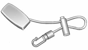
To install the adjustable comfort guide to the seatback and the safety belt:
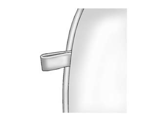
1. Locate the anchor loop on the rear outboard seatback, near the top.
2. Attach the adjustable comfort guide to the anchor loop by threading the hook through the loop.
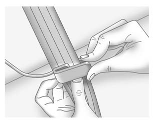
3. Place the guide over the belt, and insert the two edges of the belt into the slots of the guide.
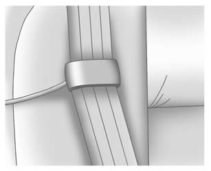
4. Be sure that the belt is not twisted and it lies flat. The elastic cord must be under the belt and the guide on top.
5. The elastic cord on the comfort guide is adjustable. You can make it longer or shorter by squeezing both ends of the plastic adjuster and pulling on the elastic cord or the guide.
6. Adjust the guide so the shoulder portion of the belt is on the shoulder and not falling off of it. The belt should be close to, but not contacting, the neck. Improper comfort guide adjustment could reduce the effectiveness of the safety belt in a crash.
Warning
A safety belt that is not properly worn may not provide the protection needed in a crash. The person wearing the belt could be seriously injured. The shoulder belt should go over the shoulder and across the chest. These parts of the body are best able to take belt restraining forces.
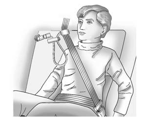
7. Buckle and position the safety belt as described previously in this section. Make sure that the shoulder belt crosses the shoulder.
To remove and store the comfort guide, squeeze the belt edges together so that the safety belt can be removed from the guide. Un-hook the guide from the loop on the seat. Store the guide in a convenient place like the glove box for the next time it is needed.
 Safety Belt Pretensioners
This vehicle has safety belt pretensioners for front outboard occupants. Although
the safety belt pretensioners cannot be seen, they are part of the safety belt assembly.
They can help tighten the ...
 Safety Belt Use During Pregnancy
Safety belts work for everyone, including pregnant women. Like all occupants,
they are more likely to be seriously injured if they do not wear safety belts.
A pregnant woman should wear a lap-sho ...
Other materials:
Replacing Airbag System Parts after a Crash
Warning
A crash can damage the airbag systems in the vehicle. A damaged airbag system
may not work properly and may not protect you and your passenger(s) in a crash,
resulting in serious injury or even death. To help make sure the airbag systems
are working properly after a crash, have them i ...
Exterior Lamp Controls
The exterior lamp control is on the instrument panel to the outboard side of
the steering column.
There are four positions:
(Off): Briefly turn to this position
to turn the automatic light control off or on again.
AUTO (Automatic): Turns the headlamps on automatically at normal brightness, ...
Brake Pedal Position Sensor Calibration
Calibration Criteria
Note: Do not apply the brake pedal during the brake pedal position
sensor calibration procedure. Any movement of the brake pedal during this
procedure will cause the calibration procedure to fail. If this occurs,
the brake pedal position sensor calibrati ...

0.0057