Chevrolet Sonic Repair Manual: Rear Wheel Bearing and Hub Replacement (Disc Brake)
Special Tools
EN–45059 Angle Meter
For equivalent regional tools, refer to Special Tools.
- Removal Procedure
-
- Raise and suitably support the vehicle. Refer to Lifting and Jacking the Vehicle.
- Remove the tire and wheel assembly. Refer to Tire and Wheel Removal
and Installation.
Caution:
Support the brake caliper with heavy mechanic wire, or equivalent, whenever it is separated from its mount and the hydraulic flexible brake hose is still connected. Failure to support the caliper in this manner will cause the flexible brake hose to bear the weight of the caliper, which may cause damage to the brake hose and in turn may cause a brake fluid leak.
- Without disconnecting the hydraulic brake flex hose, remove and support the rear brake caliper and bracket as an assembly. Refer to Rear Brake Caliper Replacement.
- Remove the rear brake rotor. Refer to Rear Brake Rotor Replacement.
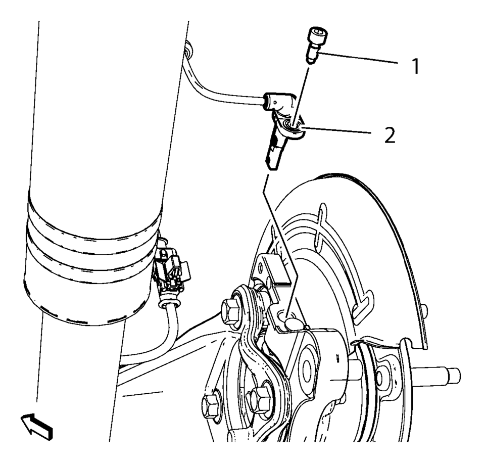
- Remove the wheel speed sensor bolt (1).
- Remove the wheel speed sensor (2).
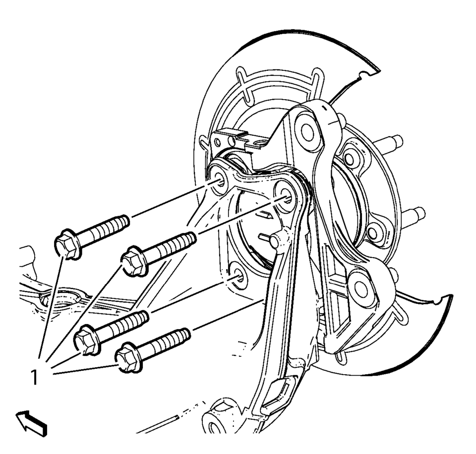
- Remove and DISCARD the 4 wheel bearing/hub mounting bolts (1).
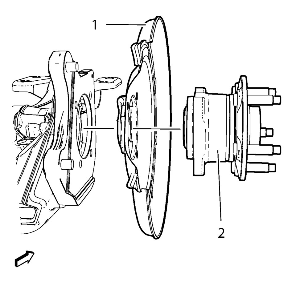
- Remove the wheel bearing/hub assembly (2) and rear brake shield (1) from the rear axle.
- Installation Procedure
-
- Position the rear brake shield (1) and wheel bearing/hub assembly (2) in the rear axle.
- Install the 4 NEW wheel bearing/hub mounting bolts (1) and tighten a
first pass to 58 Y (43 lb ft)
. Tighten the bolts evenly, in a cross-pattern.
- Install the wheel speed sensor (2).
- Install the wheel speed sensor bolt (1) and tighten to 6 Y (53 lb in)
.
- Install the brake rotor. Refer to Rear Brake Rotor Replacement.
- Install the brake caliper and bracket as an assembly. Refer to Rear Brake Caliper Replacement.
- Install the tire and wheel assembly. Refer to Tire and Wheel Removal and Installation.
- Lower the vehicle.
Caution:
Refer to Fastener Caution.
 Hub/Axle Flange and Wheel Stud Runout Inspection
Special Tools
GE-8001 Dial Indicator Set , or equivalent
Raise and support the vehicle. Refer to Lifting and Jacking the Vehicle.
Mark the location of the wheels to the wheel studs and mar ...
 Rear Wheel Bearing and Hub Replacement (Drum Brake)
Rear Wheel Bearing and Hub Replacement
Callout
Component Name
Preliminary Procedures
Raise and support the vehicle. Refer to Liftin ...
Other materials:
Instrument Panel Illumination Control
This feature controls the brightness of the instrument panel controls and infotainment
display screen. The thumbwheel is to the left of the steering column on the instrument
panel.
(Instrument Panel Brightness): Move
the thumbwheel up or down and hold, to brighten or dim the instrument pane ...
Brakes
If the overheat warning no longer displays, the vehicle can be driven. Continue
to drive the vehicle slowly for about 10 minutes. Keep a safe vehicle distance from
the vehicle in front. If the warning does not come back on, continue to drive normally
and have the cooling system checked for pro ...
Fuel Tank Fuel Pump Module Replacement (Steel Tank)
Special Tools
EN-48279 Fuel Sender Lock Ring Wrench
For equivalent regional tools, refer to Special Tools.
Removal Procedure
Relieve the fuel system pressure. Refer to Fuel Pressure Relief.
Remove the fuel tank. Refer to Fuel Tank Replacement.
Disconnect the ...

0.0072