Chevrolet Sonic Repair Manual: Remote Control Door Lock, Theft Deterrent, and Remote Start Transmitter Package Installation
- Installation Instructions Part Number
-
22880351
20997377
95198137
22901614
92233547
Kit Usage
This kit adds remote start to vehicles without option BTV. The vehicle must also have an automatic transmission. Both can be verified by using the GM Vehicle Inquiry System (GMVIS). Adding remote vehicle start requires programming of the vehicle. This is done with using the Service Programming System. The installer must call TCSC (1–888–337–1010) to obtain a VCI number. The TCSC will provide a Vehicle Configuration index (VCI). The VCI is good for only one specific Vehicle Identification Number (VIN). You must have the vehicle’s VIN that will be upgraded and the Authorization Code from label on the installation sheet included with the kit. This will allow you to access the software to enable the remote vehicle start option.
|
Qty |
Description |
|---|---|
|
2 |
Transmitters |
|
1 |
Installation Instructions |
Procedure
Note:
Please review this entire procedure before trying to perform it.
Note:
When calling the TCSC, you must use the Authorization Code from the kit.
- Updating the Transmitter to a Coded Key
-
Note:
Updating the transmitter to a coded key applies to the United States and Canada only.
Export dealers are to contact their local Technical Assistance Center (TAC) for further information.
Due to the uniqueness of the ignition/door lock key, special equipment is required to cut a key.
For equipment details, refer to Service Bulletin #09-00-89-029J: Key Cutting Procedure for Obtaining Replacement Key.
If you do not have the required equipment, use Flip Key Blade Fixture Tool BO-51098 to swap coded key from OE Transmitter and install on Accessory Transmitter. Refer to Door Lock and Ignition Lock Folding Key Blade Removal and Installation.
Tip:
The new key and transmitter will need to be programmed to the vehicle. Refer to Programming Vehicle at the end of these instructions for details.
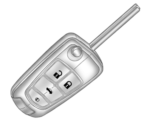
Note:
Graphic details vary with vehicle configuration.
- Special Tools
-
- Scan Tool with capability of communicating on GMLAN
- Service Programming System (SPS – TIS2WEB or equivalent)
- J - 46079 Tire Pressure Monitor Diagnostic Tool
- BO - 51098 Flip Key Blade Fixture
- Programming Vehicle
- Body Control Module Programming and Setup
Reprogramming ECU
Note:
- DO NOT program a control module unless directed to by a service procedure or a service bulletin. If the ECU is not properly configured with the correct calibration software, the ECU will not control all of the vehicle features properly.
- Ensure the programming tool is equipped with the latest software and is securely connected to the data link connector. If there is an interruption during programming, programing failure or ECU damage may occur.
- Stable battery voltage is critical during programming. Any fluctuation, spiking, over voltage or loss of voltage will interrupt programming. Install the EL - 49642 SPS Programming Support Tool to maintain system voltage. If not available, connect a fully charged 12V jumper or booster pack disconnect from the AC voltage supply. DO NOT connect a battery charger.
- Turn OFF or disable systems that may put a load on the vehicles battery such as; interior lights, exterior lights (including daytime running lights), HVAC, radio, etc.
- During the programming procedure, follow the SPS prompts for the correct ignition switch position.
- Clear DTCs after programming is complete. Clearing powertrain DTCs will set the Inspection/Maintenance (I/M) system status indicators to NO.
To program an existing BCM, perform the following procedure:
- Install EL - 49642 SPS programming support tool.
- Access the Service Programming System (SPS) and follow the on-screen instructions.
- On the SPS Supported Controllers screen, select BCM Body Control Module – programming and follow the on-screen instructions.
- Perform the following for the appropriate ignition type prior to proceeding with the next step:
- Key Ignition System: key in the ignition and any additional keys must be away from the vehicle at least 3 meters.
- Push Button Start System: Keyless entry transmitter must be
in the console programming pocket. Refer to the Help section button on the
SPS Immobilizer Setup screen for the exact pocket location. All
additional transmitters must be away from the vehicle at least 3 meters.
Note:
The following programming step may take between 10 - 12 min. and progress will appear to have stopped during this process. This is a normal security timer response and a restart should not be performed. If the DTC B389A set immediately after programming a replacement BCM, the Immobilizer Learn procedure was not properly completed. The Immobilizer Learn procedure needs to be performed again.
Note:
Deleting existing Keys or Transponders without remote start button – this will render the subject key(s) inoperable. This step will however, allow the new transponders to correspond with the memory seat locations. – Skip Step 5 if the vehicle is NOT equipped with Memory Seats.
- On the SPS Supported Controllers screen, select IMMO Immobilizer Learn - Setup. On the next screen, select (Program Transponder or Remote Key (Delete). To Delete existing keys and remotes, follow the on-screen instructions. When Delete existing keys and remote is complete, follow on–screen instructions and exit the Immobilizer learn mode. repeat this step to delete any remaining remotes.
Note:
Adding new Keys or Transponders with remote start button.
- On the SPS Supported Controllers screen, select IMMO Immobilizer Learn - Setup. on the next screen, select (Program Transponder or Remote Key (Add). To add existing Transponder or Remote Keys, follow the on-screen instructions. When Immobilizer Learn is complete, press the Unlock button on the keyless entry transmitter to allow the keyless entry transmitter to exit the Immobilizer Learn mode. Repeat this step to add any additional remotes.
Note:
When performing the Tire Pressure Monitor Sensor Learn during BCM setup, the EL-46079 tire pressure monitor diagnostic tool must be used to activate each tire pressure sensor for vehicles with UJM.
- On the SPS Supported Controllers screen, select BCM Body Control Module - Setup and follow the on-screen instructions.
- Check the driver information center display for additional messages regarding further calibration instructions. If there are no additional driver information center instructions present, programming is complete.
- At the end of programming, choose the “Clear All DTCs” function on the SPS screen.
- If ABS, Traction Control and/or Stabilitrak indicators are ON and DTC C0161 is set in the electronic brake control module after performing BCM programming and setup, do the following;
- Disconnect the scan tool from the data link connector.
- Ignition OFF, all access doors closed, all vehicle systems OFF, and all keys at least 3 meters away from the vehicle. it may take up to 2 minutes to power down.
- Ignition ON, verify DTC C0161 is in history. If not, repeat the above step to make sure the vehicle is in sleep mode.
- Use the scan tool to clear the DTCs.
- Unsuccessful Programming Recovery
-
In the event of an interrupted or unsuccessful programming event, perform the following steps:
- DO NOT turn the ignition OFF. Ensure that all ECU, DLC and programming tool connections are secure and the TIS terminal operating software is up to date.
- Attempt to reprogram the ECU.
- If the ECU can still not be programmed, turn the ignition OFF for at least one minute.
- Turn the ignition ON and attempt to reprogram the ECU.
The ECU should program.
If the ECU still cannot be programmed, replace the ECU.
 Generator Pulley Replacement (LUV)
Generator Pulley Replacement
Callout
Component Name
Preliminary Procedure
Remove the generator. Refer to Generator Replacement. ...
 SIR Disabling and Enabling
SIR component location affects how a vehicle should be serviced. There are parts
of the SIR system installed in various locations around a vehicle. To find the location
of the SIR components refer ...
Other materials:
Front Side Door Window Regulator Motor Replacement
Front Side Door Window Regulator Motor Replacement
Callout
Component Name
Warning: Refer to Glass and Sheet Metal Handling Warning.
Preliminary Procedure
Remove the front side door window regulator. Front Side ...
Front Bumper Upper Impact Bar Replacement
Front Bumper Upper Impact Bar Replacement
Callout
Component Name
Preliminary Procedure
Remove the front bumper fascia. Refer to Front Bumper Fascia Replacement.
1
Front Bumper Impact Bar Bolt (Qt ...
Instrument Panel Airbag Arming Status Display Replacement
Instrument Panel Airbag Arming Status Display Replacement
Callout
Component Name
Preliminary Procedure
Remove the heater and air conditioning control. Refer to Heater and Air
Conditioning Control Replacement.
...

0.0074