Chevrolet Sonic Repair Manual: Starter Replacement (LUW)
- Removal Procedure
-
- Disconnect the negative battery cable. Refer to Battery Negative Cable Disconnection and Connection.
- Raise and support the vehicle. Refer to Lifting and Jacking the Vehicle.
- Remove the drivetrain and front suspension frame skid plate. Refer to Drivetrain and Front Suspension Frame Skid Plate Replacement.
- Remove the intake manifold brace fasteners (1) and remove the intake manifold brace (2).
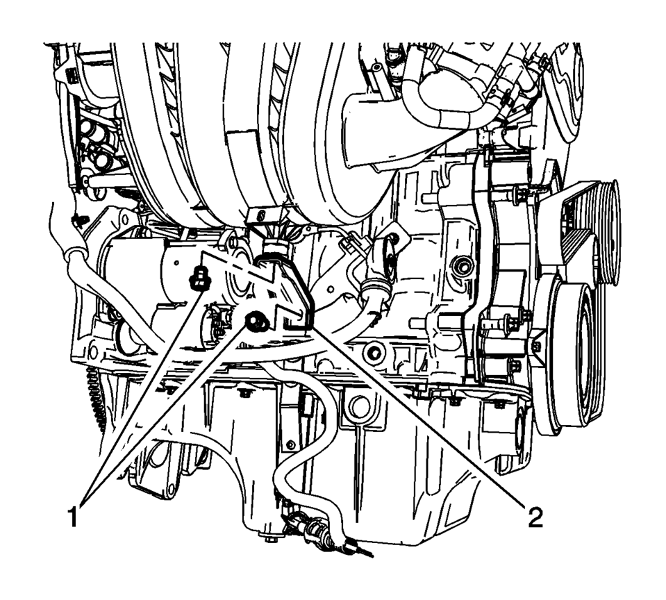
- Remove the starter solenoid battery positive fastener (2) and the starter mounting stud/fastener (1).
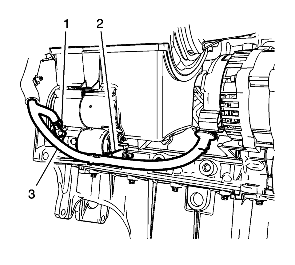
- Remove the battery positive and negative cable (3) from the starter.
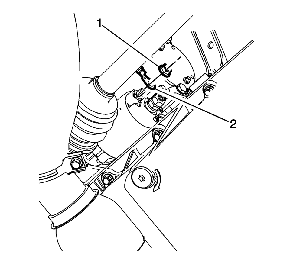
- Remove the starter solenoid fastener (1) and the engine harness terminal (2) from the starter solenoid.
- Remove the starter mounting fastener (1) and the starter (3) from the vehicle.
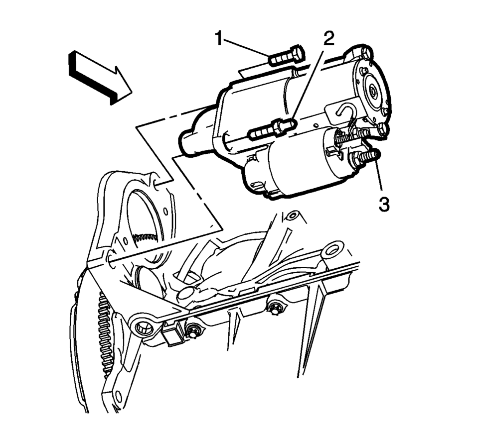
Note:
The starter mounting fastener can be accessed from the top of the engine, with the battery tray removed.
- Installation Procedure
-
- Install the starter (3) into position and tighten the starter mounting
fastener (1) to 25 Y (18 lb ft)
.
- Install the engine harness terminal (2) to the starter solenoid and
tighten the solenoid fastener (1) to 9 Y (80 lb in)
.
- Install the battery negative cable terminal and the starter mounting
stud/fastener (1) to the starter. Tighten to 25 Y (18 lb ft)
.
- Install the positive battery cable terminal to the starter solenoid
and tighten the fastener (2) to 9 Y (80 lb in)
.
- Install the intake manifold brace (2) and mounting fasteners (1). Tighten
to 8 Y (71 lb in)
.
- Install the drivetrain and front suspension frame skid plate. Refer to Drivetrain and Front Suspension Frame Skid Plate Replacement.
- Connect the negative battery cable. Refer to Battery Negative Cable Disconnection and Connection.
Caution:
Refer to Fastener Caution.
- Install the starter (3) into position and tighten the starter mounting
fastener (1) to 25 Y (18 lb ft)
 Starter Replacement (LUV)
Removal Procedure
Disconnect the battery negative cable. Refer to Battery Negative Cable
Disconnection and Connection.
Raise and support the vehicle. Refer to Lifting and J ...
 Starting System Description and Operation
The starter motors are non-repairable starter motors. They have pole pieces that
are arranged around the armature. Both solenoid windings are energized. The pull-in
winding circuit is completed to ...
Other materials:
Airbag Front Passenger Presence Sensor Replacement
Airbag Front Passenger Presence Sensor Replacement
Callout
Component Name
Warning: Replace the passenger presence system as a complete
assembly to prevent possible injury to the occupant. All the components
in the se ...
HVAC System Control Module Programming and Setup
Note:
DO NOT program a control module unless directed to by a service procedure
or a service bulletin. If the control module is not properly configured
with the correct calibration software, the control module will not control
all of the vehicle features properly.
Ensure th ...
Transmission Assemble (Gen 1)
Special Tools
3-9506289 Universal Adapter
R-0007758 Holding Fixture
S-9407197 Differential Rotating Tool
S-9407198 Differential Bearing Race Wrench
For equivalent regional tools, refer to Special Tools.
Install the clutch and differential housing assembly (1)
onto ...

0.0062