Chevrolet Sonic Repair Manual: Steering Gear Replacement
|
Callout |
Component Name |
|---|---|
|
Caution: With wheels of the vehicle facing straight ahead, secure the steering wheel utilizing steering column anti-rotation pin, steering column lock, or a strap to prevent rotation. Locking of the steering column will prevent damage and a possible malfunction of the SIR system. The steering wheel must be secured in position before disconnecting the following components:
After disconnecting these components, do not rotate the steering wheel or move the front tires and wheels. Failure to follow this procedure may cause the SIR coil assembly to become un-centered and cause possible damage to the SIR coil. If you think the SIR coil has become un-centered, refer to your specific SIR coil’s centering procedure to re-center SIR Coil.
|
|
|
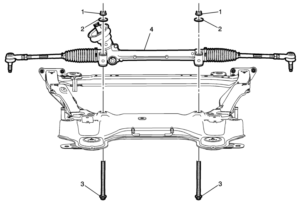
1 |
Steering Gear Nut (Qty: 2) Procedure
During installation, hold the steering gear nuts while tightening the steering gear bolts. |
|
2 |
Steering Gear Washer (Qty: 2) |
|
3 |
Steering Gear Bolt (Qty: 2) Warning: This component is equipped with torque-to-yield fasteners. Install a NEW torque-to-yield fastener when installing this component. Failure to replace the torque-to-yield fastener could cause bodily injury and damage to the vehicle or component. Caution: Refer to Fastener Caution
Special Tools
EN-45059 Angle Meter For equivalent regional tools, refer to Special Tools. |
|
4 |
Steering Gear Procedure
|
 Steering Gear Boot Replacement
Special Tools
CH-804 Tensioner
For equivalent regional tools, refer to Special Tools.
Removal Procedure
Raise and support the vehicle. Refer to Lifting and Jacking the Vehicl ...

Other materials:
Charging System Light
This light will come on briefly when the ignition is turned on, and the engine
is not running, as a check to show it is working.
It should go out when the engine is started. If it stays on, or comes on while
driving, there may be a problem with the electrical charging system. Have it checked ...
Front Side Door Upper Front Trim Panel Replacement
Front Side Door Upper Front Trim Panel Replacement
Callout
Component Name
1
Front Side Door Upper Front Trim Panel Assembly
Procedure
Use the appropriate plastic trim tool to aid in the removal of the door
tri ...
Brake Drum Refinishing
Special Tools
CH-41013 Rotor Resurfacing Kit
CH-42450-A Wheel Hub Resurfacing Kit
For equivalent regional tools, refer to Special Tools.
Warning: Refer to Brake Dust Warning.
The brake drums do not require refinishing as part of routine brake system
service. Do not refinis ...

0.0054