Chevrolet Sonic Repair Manual: Steering Knuckle Replacement
- Removal Procedure
-
- Raise and support the vehicle. Refer to Lifting and Jacking the Vehicle.
- Remove the tire and wheel assembly. Refer to Tire and Wheel Removal and Installation.
- Remove the wheel speed sensor from the steering knuckle. Refer to Front Wheel Speed Sensor Replacement.
- Separate the wheel drive shaft from the steering knuckle. Refer to Front Wheel Drive Shaft Replacement.
- Remove the brake rotor from the steering knuckle. Refer to Front Brake Rotor Replacement.
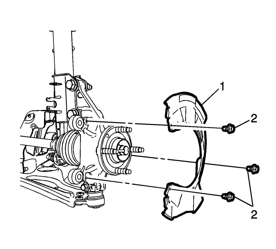
- Remove the front brake dust shield bolts (2) and the shield (1).
- Remove the lower ball joint bolt and nut from the steering knuckle. Refer to Lower Control Arm Replacement.
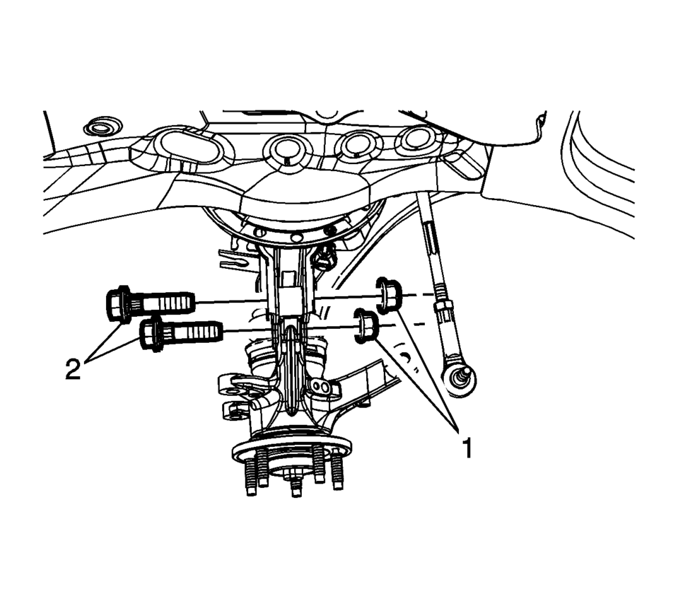
- Remove the bolts (2) and the nuts (1) from the front strut to the steering knuckle. Refer to Strut Assembly Removal and Installation
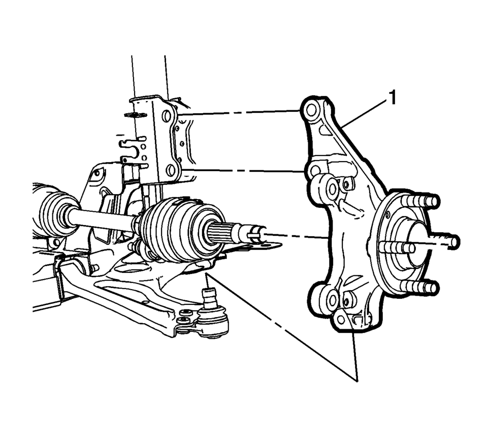
- Remove the steering knuckle assembly (1) from the vehicle.
- Remove the wheel bearing and hub assembly from the steering knuckle. Refer to Front Wheel Bearing and Hub Replacement.
- Installation Procedure
-
- Install the wheel bearing and hub assembly in the steering knuckle. Refer to Front Wheel Bearing and Hub Replacement.
- Position the steering knuckle (1) in the front strut and lower ball joint.
- Install the bolts (2) and the nuts (1) from the front strut assembly to the steering knuckle. Refer to Strut Assembly Removal and Installation.
- Install the lower ball joint bolt and nut to the steering knuckle. Refer to Lower Control Arm Replacement.
- Install the front brake dust shield (1) bolts (2) and the bolts to
9 Y (80 lb in)
.
- Install the brake rotor on the steering knuckle. Refer to Front Brake Rotor Replacement.
- Install the NEW wheel drive shaft nut. Refer to Front Wheel Drive Shaft Replacement.
- Install the wheel speed sensor in the steering knuckle. Refer to Front Wheel Speed Sensor Replacement.
- Install the tire and wheel assembly the tire and wheel assembly. Refer to Tire and Wheel Removal and Installation.
- Remove the supports and lower the vehicle.
- Check the front wheel alignment measurements, if the vehicle had a camber adjustment repair. Refer to Wheel Alignment Specifications.
Caution:
Refer to Fastener Caution.
 Tire and Wheel Assembly-to-Hub/Axle Flange Match-Mounting
Note: After remounting a tire and wheel assembly to a hub/axle flange,
remeasure the tire and wheel assembly on-vehicle runout in order to verify that
the amount of runout has been reduced an ...
 Liftgate Strut Replacement
Liftgate Strut Replacement
Callout
Component Name
1
Liftgate Strut
Warning: When a lift gate hold open device is ...
Other materials:
Remote Control Door Lock Receiver Replacement
Remote Control Door Lock Receiver Replacement
Callout
Component Name
Preliminary Procedure
Remove the windshield outside moisture sensor cover. Refer to Windshield
Outside Moisture Sensor Cover Replacement.
...
Driver Information Center (DIC)
The DIC displays information about your vehicle. It also displays warning messages
if a system problem is detected. See Vehicle Messages. All messages appear in the
DIC display in the instrument cluster.
DIC Operation and Displays
The DIC has different displays which can be accessed b ...
Warning/indicator lights (red)
Brake warning light
or
In the Nissan Armada, the brake warning light is a critical safety indicator
that helps monitor the condition of the braking system. When the ignition switch
is turned to the ON position, this light should illuminate briefly for a few seconds
and then turn off, ...

0.0049