Chevrolet Sonic Repair Manual: Steering Linkage Inner Tie Rod Inspection
Special Tools
GE-8001 Dial Indicator Set
For equivalent regional tools, refer to Special Tools.
- Turn the ignition key to the ON position with the engine OFF.
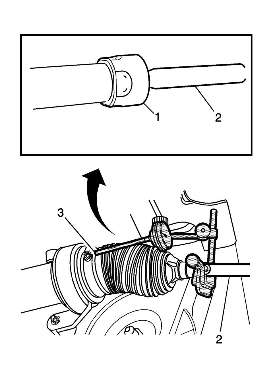
- With the aid of an assistant, turn the steering wheel to the full stop position and hold the steering wheel in that position until the test is complete. Part of the steering linkage inner tie rod (2) being tested should be inside the steering gear housing. The inner tie rod housing (1) being tested should be inside the steering gear housing and seated against the steering stop.
- Raise and support the vehicle. Refer to Lifting and Jacking the Vehicle.
- If there is not a good location for the GE-8001 dial indicator pointer at the steering gear housing, install a large worm gear hose clamp (3) to the steering gear housing over the larger steering gear boot clamp and align the clamp so that the screw can be a location for the GE-8001 dial indicator pointer.
- Install the GE-8001 dial indicator between the inner tie rod and the steering gear housing or the worm gear clamp in such a way as to measure the lash between the inner tie rod and the steering gear housing. The lash between the inner tie rod and the steering gear housing is equal to the lash between the inner tie rod and the inner tie rod housing because the inner tie rod housing is inside the steering gear housing during this procedure.
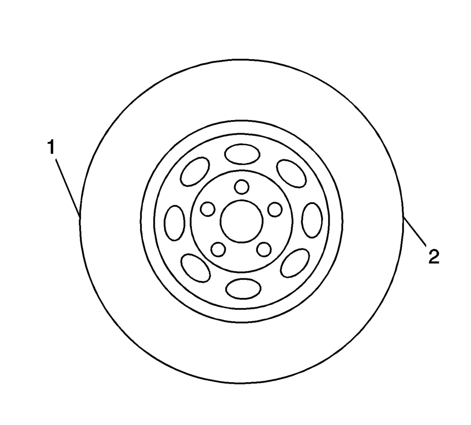
- Grasping the tire at the 3 o'clock (2) and 9 o'clock (1) positions, gently push in on one side of the tire in order to remove any lash.
- Zero the GE-8001 dial indicator .
- On the same side of the tire previously pushed in, gently pull out and measure the lash.
- Record the measurement shown on the GE-8001 dial indicator .
- If the measured value exceeds 0.5 mm (0.02 in), replace the inner tie rod. Refer to Steering Linkage Inner Tie Rod Replacement.
- Repeat the procedure for the other side.
Note:
This inspection procedure does not supersede local government required inspections that have more stringent requirements.
Note:
Only move the tire enough to feel any lash between the inner tie rod and the inner tie rod housing without moving the steering gear rack.
 Steering Gear Replacement
Steering Gear Replacement
Callout
Component Name
Caution: With wheels of the vehicle facing straight ahead,
secure the st ...
 Steering Linkage Inner Tie Rod Replacement
Steering Linkage Inner Tie Rod Replacement
Callout
Component Name
Preliminary Procedures
Raise and support the vehicle. Refer to Li ...
Other materials:
Manual Transmission
The vehicle may be equipped with a 5-speed or 6-speed manual transmission.
Caution
Shifting the vehicle initially into any gear other than 1 (First) or R (Reverse)
can damage the clutch. Shift the manual transmission in the proper sequence, and
time the gear shifting with the accelerator to ...
Front Seat Back Recliner Handle Replacement
Front Seat Back Recliner Handle Replacement
Callout
Component Name
1
Front Seat Recliner Handle Cover Cap
Procedure
Use a flat-bladed tool to release the handle cover from the handle assembly.
...
Control Solenoid Valve and Transmission Control Module Assembly Installation
Control Solenoid Valve and Transmission Control Module Assembly Installation
Callout
Component Name
1
Control Solenoid Valve Assembly Filter Plate
Caution: Use care when removing or installing the filter plate
...

0.0082