Chevrolet Sonic Repair Manual: Steering Linkage Outer Tie Rod Inspection
Special Tools
GE-8001 Dial Indicator Set
For equivalent regional tools, refer to Special Tools.
- Inspect the outer tie rod seal. If the outer tie rod seal is torn, replace the outer tie rod. Refer to Steering Linkage Outer Tie Rod Replacement.
- Raise the side of the vehicle being inspected with a floor jack while maintaining contact between the opposite wheel and the shop floor. Support the lower control arm with a floor jack stand as far outboard as possible and remove the floor jack. Refer to Lifting and Jacking the Vehicle.
- Install the GE-8001 dial indicator between the outer tie rod and the steering knuckle as shown in the graphic. Note that the tire and wheel assembly is shown removed only for clarification of the GE-8001 dial indicator position.
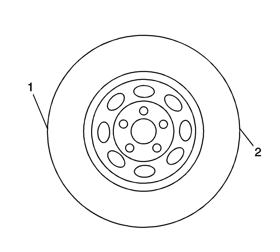
- Grasping the tire at the 3 o'clock (2) and 9 o'clock (1) positions, gently push in on one side of the tire to remove any lash.
- Zero the GE-8001 dial indicator .
- On the same side of the tire previously pushed inwards, gently pull outwards and measure the lash.
- Record the measurement shown on the GE-8001 dial indicator .
- If the measured value exceeds 0.5 mm (0.02 in), replace the outer tie rod. Refer to Steering Linkage Outer Tie Rod Replacement.
- Repeat the procedure for the other side.
Note:
This inspection procedure does not supersede local government required inspections that have more stringent requirements.

 Steering Linkage Inner Tie Rod Replacement
Steering Linkage Inner Tie Rod Replacement
Callout
Component Name
Preliminary Procedures
Raise and support the vehicle. Refer to Li ...
 Steering Linkage Outer Tie Rod Replacement
Steering Linkage Outer Tie Rod Replacement
Callout
Component Name
Preliminary Procedures
Raise and support the vehicle. Refer to Li ...
Other materials:
Malfunction Indicator Lamp
A computer system called OBD II (On-Board Diagnostics-Second Generation) monitors
the operation of the vehicle to ensure emissions are at acceptable levels, helping
to maintain a clean environment. The malfunction indicator lamp comes on when the
vehicle is placed in ON/RUN, as a check to show ...
Rear Axle Replacement
Removal Procedure
Raise and support the vehicle. Refer to Lifting and Jacking the Vehicle.
Remove the tires and wheel assembly. Refer to Tire and Wheel Removal
and Installation.
Remove the park brake cables from the rear axle. Refer to Parking Brake
Cable Replacement. ...
Manifold Absolute Pressure Sensor Replacement
.-
Manifold Absolute Pressure Sensor Replacement
Callout
Component Name
1
Manifold Absolute Pressure Sensor Fastener
Caution: Refer to Fastener Caution
Tighten
6 Y (54 lb in)
...

0.006