
Chevrolet Sonic Repair Manual: Steering Linkage Outer Tie Rod Replacement
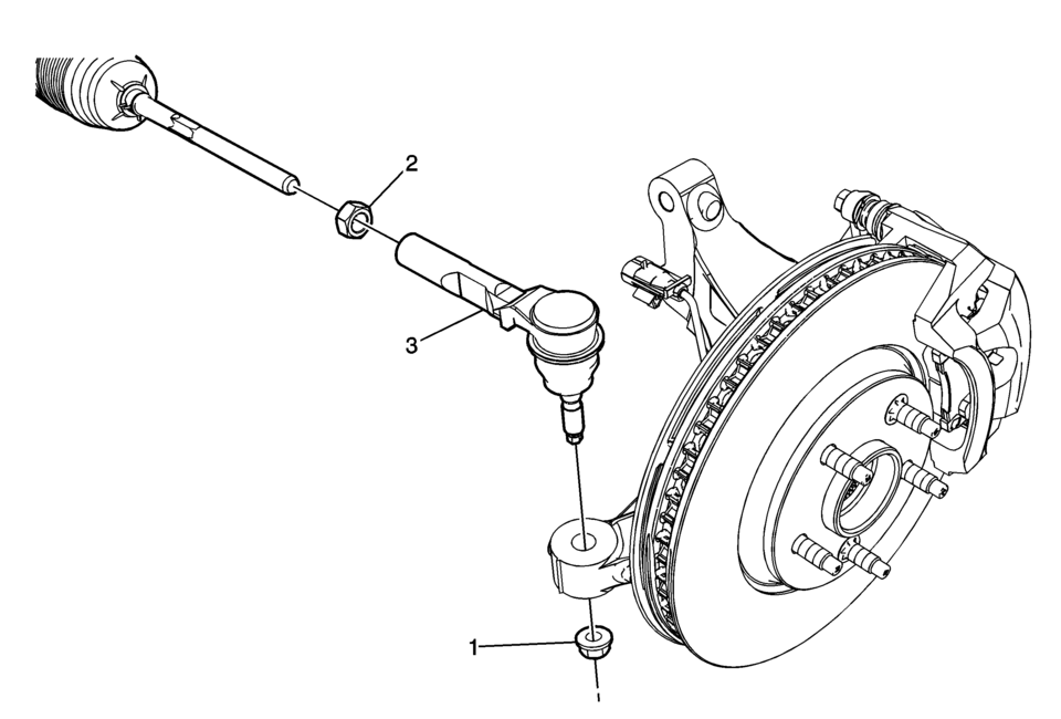
|
Callout |
Component Name |
|---|---|
Preliminary Procedures
|
|
|
1 |
Steering Linkage Outer Tie Rod Nut Caution: Refer to Fastener Caution. Procedure
Use the EN-45059 meter in order to tighten the outer tie rod nut to the specification. Tighten
Special Tools
EN-45059 Angle Meter For equivalent regional tools, refer to Special Tools. |
|
2 |
Steering Linkage Inner Tie Rod Nut Procedure
|
|
3 |
Steering Linkage Outer Tie Rod Caution: Do not free the ball stud by using a pickle fork or a wedge-type tool. Damage to the seal or bushing may result.
Special Tools
CH-161-B Bearing Puller For equivalent regional tools, refer to Special Tools. |
 Steering Linkage Outer Tie Rod Inspection
Special Tools
GE-8001 Dial Indicator Set
For equivalent regional tools, refer to Special Tools.
Note: This inspection procedure does not supersede local government
required inspection ...
 Steering Control
...
Other materials:
Crankshaft and Bearing Removal
Identify all the connecting rod bearing caps (1).
Remove the 4 bolts.
Remove the connecting rod bearing caps 1 and 4 (1).
Turn the crankshaft through 180°.
Remove the 4 bolts.
Remove the connecting rod bearing caps 2 and 3 ( ...
Fuel Pressure Sensor Replacement
Fuel Pressure Sensor Replacement
Callout
Component Name
Preliminary Procedure
Relieve the fuel system pressure. Refer to
Fuel Pressure Relief.
Remove the air cleaner assembly. Refer to
Air Cleaner Assembly Replacement. ...
Heated seats
Basic information
WARNING
In the Nissan Armada, avoid using seat heaters if occupants are unable to
sense temperature changes or pain. Improper use may result in overheating and serious
injury.
CAUTION
Do not operate the heated seats in the Nissan Armada for extended periods
when not i ...

0.0065