Chevrolet Sonic Repair Manual: Strut Assembly Removal and Installation
Special Tools
CH 49375 Strut Rod Nut Socket
For equivalent regional tools, refer to Special Tools
- Removal Procedure
-
- Remove the air inlet grille panel. Refer to Air Inlet Grille Panel Replacement.
- Raise and support the vehicle. Refer to Lifting and Jacking the Vehicle.
- Remove the tire and wheel assembly. Refer to Tire and Wheel Removal and Installation.
- Remove the stabilizer shaft link from the front strut assembly. Refer to Stabilizer Shaft Link Replacement.
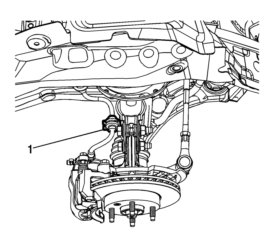
- Remove the front brake hose (1) from the front strut assembly.
- Remove the speed sensor wring harness from the front strut assembly, if needed.
- Remove the outer tie rod end from the steering knuckle. Refer to Steering Linkage Outer Tie Rod Replacement.
- Support the lower control arm with a jack stand.
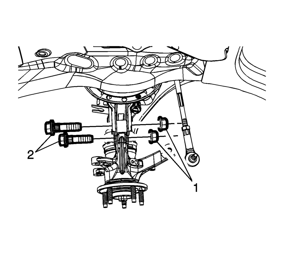
- Remove the front strut nut (1) and the bolt (2) from the front strut.
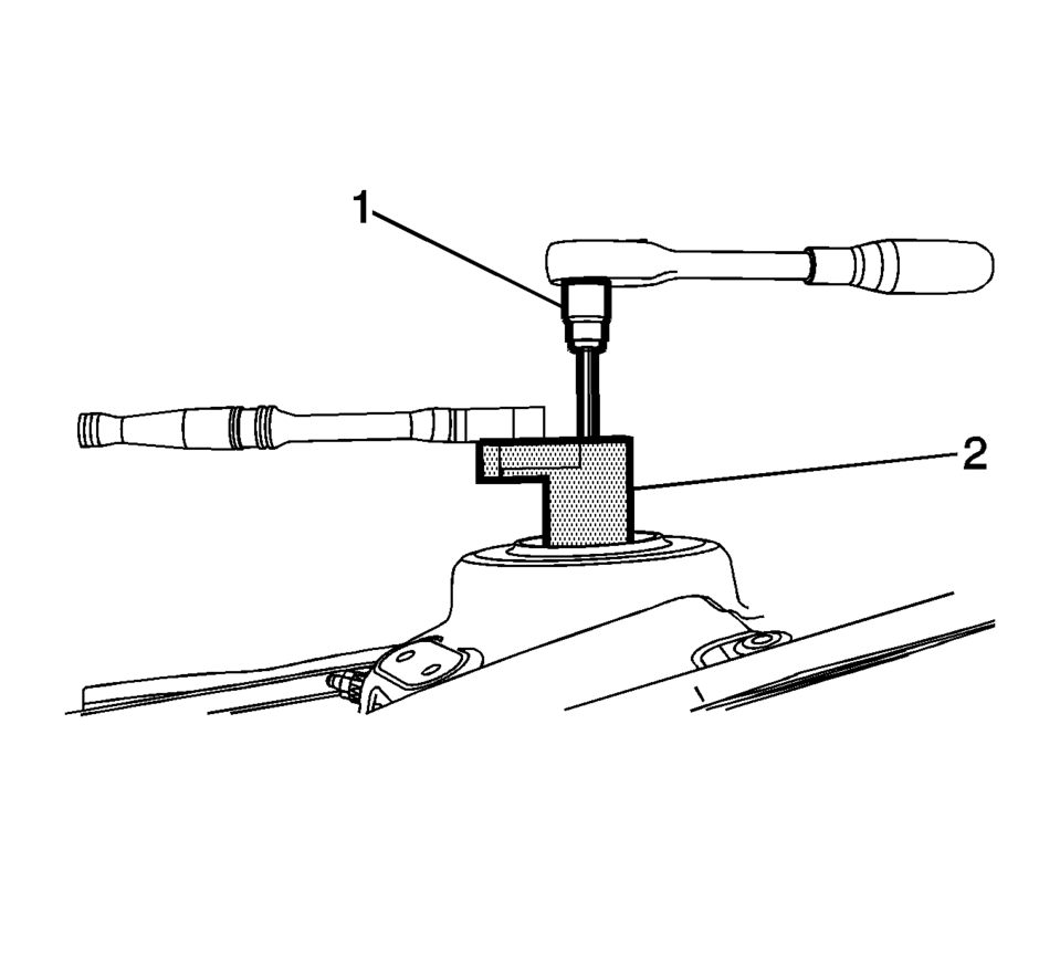
- Using the CH 49375 socket (2) and the proper size Torx® wrench, loosen the front strut nut.
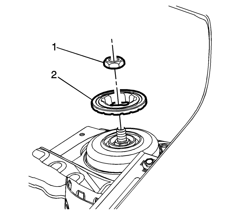
- Remove the front strut nut (1) and the retaining plate (2).
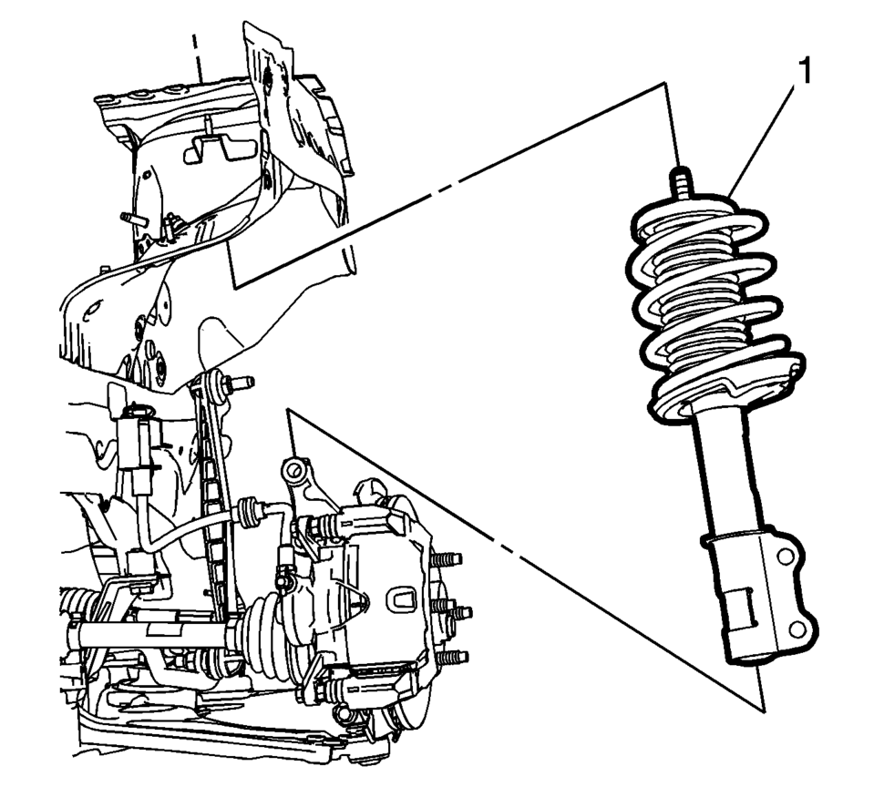
- Remove the front strut assembly from the vehicle (1).
- If removing the front strut assembly to service any of the front strut components, refer to Strut, Strut Component, or Spring Replacement.
- Installation Procedure
-
- Position the front strut assembly (1) in the vehicle.
- Install the front strut nut (1) and the retaining plate (2).
- Using the CH 49375 socket (2) and the proper size Torx® wrench
to hold the strut shaft, tighten the nut to 65 Y (48 lb ft)
.
- Install the front strut nut (1) and the bolt (2) from the front strut
and tighten the nut to 110 Y (82 lb ft)
.
- Install the stabilizer shaft link in the front strut assembly. Refer to Stabilizer Shaft Link Replacement.
- Remove the jack stand from the lower control arm.
- Install the outer tie rod end in the steering knuckle. Refer to Steering Linkage Outer Tie Rod Replacement.
- Install the speed sensor wiring harness on the front strut assembly, if needed.
- Install the front brake hose (1) on the front strut assembly.
- Install the tire and wheel assembly. Refer to Tire and Wheel Removal and Installation.
- Remove the support and lower the vehicle.
- Install the air inlet grille panel. Refer to Air Inlet Grille Panel Replacement.
Caution:
Refer to Fastener Caution.
 Liftgate Strut Replacement
Liftgate Strut Replacement
Callout
Component Name
1
Liftgate Strut
Warning: When a lift gate hold open device is ...
 Strut, Strut Component, or Spring Replacement
Disassembly Procedure
Remove the strut assembly from the vehicle. Refer to Strut Assembly
Removal and Installation.
Note: The spring is compressed when the strut move ...
Other materials:
Hydraulic Brake System Flushing
Warning: Refer to Brake Fluid Irritant Warning.
Caution: Refer to Brake Fluid Effects on Paint and Electrical Components
Caution.
Inspect the brake fluid for the following conditions, indicating brake fluid
contamination:
Fluid separation, indicating 2 types of fl ...
Motion-activated liftgate
Example
Example
Basic information
The Nissan Armada features a convenient motion-activated liftgate system that
allows hands-free operation using a simple foot gesture beneath the rear bumper.
The kick motion sensor a is positioned on the left side under the rear bumper.
When you per ...
Speed Limit Assist (a feature of ProPILOT Assist 1.1 and 2.1)
Speed Limit Assist in the Nissan Armada is an advanced functionality integrated
within the ProPILOT Assist 1.1 and 2.1 systems. This feature works in conjunction
with the built-in map locator and Traffic Sign Recognition (TSR) system to help
drivers maintain compliance with posted speed limits ...

0.007