Chevrolet Sonic Repair Manual: Strut, Strut Component, or Spring Replacement
- Disassembly Procedure
-
- Remove the strut assembly from the vehicle. Refer to Strut Assembly Removal and Installation.
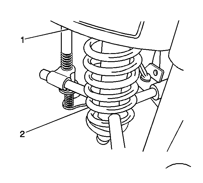
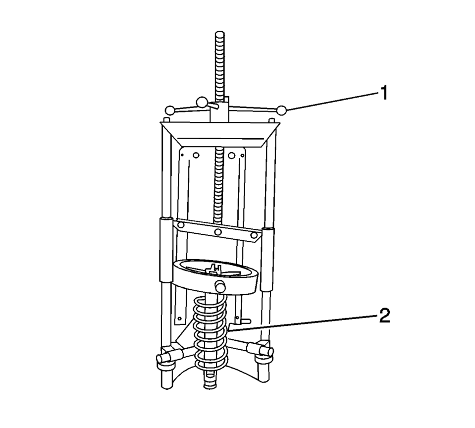
- Install the strut assembly (2) in a suitable spring compressor (1) and compress the front spring.
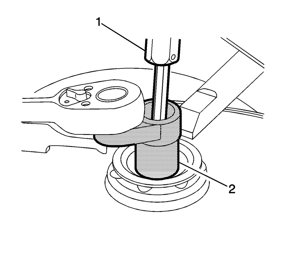
- Use a suitable bit (1) and socket (2) to loosen the front suspension strut mount nut.
- Slowly loosen the spring compressor (2) to remove the front suspension strut components to be serviced.
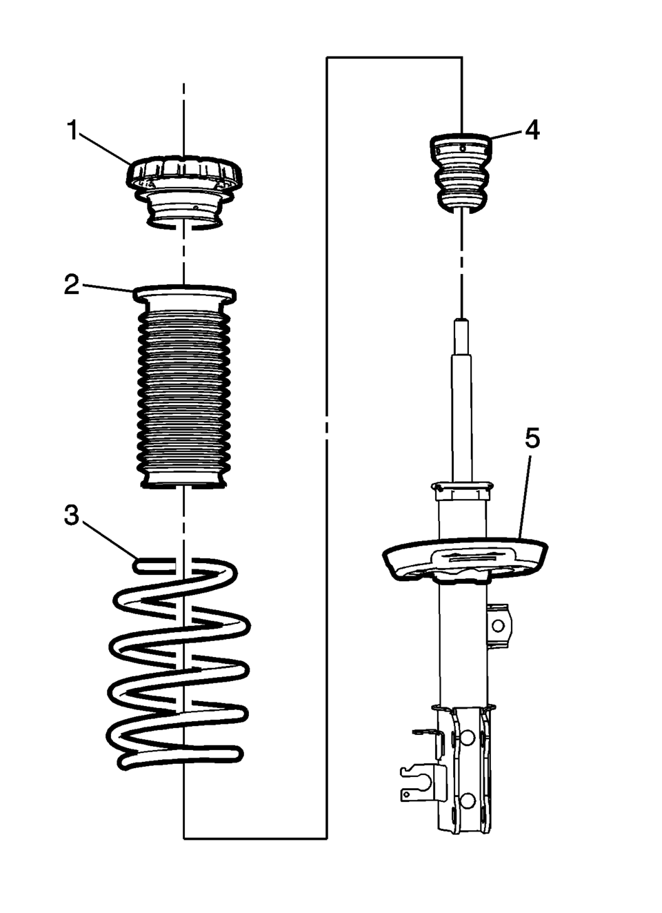
- Remove the front suspension strut mount assembly (1), front spring insulator (2), front spring (3), front suspension strut bumper (4) and the front strut (5) from the spring compressor.
Note:
The spring is compressed when the strut moves freely.
(((((((l(((((((((((i
- Assembly Procedure
-
- Install the front suspension strut (5), front suspension strut bumper (4), front spring (3), front spring insulator (2) and the front suspension strut mount assembly (1) in the spring compressor.
- Use the spring compressor (1) to compress the front spring (2).
- Install the front suspension strut mount nut and tighten as much as possible by hand.
- Use a suitable bit (1) and socket (2) to tighten the front suspension
strut mount nut to 65 Y (48 lb ft)
.
- Remove the strut assembly from the spring compressor.
- Install the strut assembly. Refer to Strut Assembly Removal and Installation.
(((((((l(((((((((((i
Caution:
Refer to Fastener Caution.
 Strut Assembly Removal and Installation
Special Tools
CH 49375 Strut Rod Nut Socket
For equivalent regional tools, refer to Special Tools
Removal Procedure
Remove the air inlet grille panel. Refer to Air Inlet Grill ...
 Shock Absorber Disposal
Warning: Use the proper eye protection when drilling to prevent metal
chips from causing physical injury.
Clamp the strut in a vise horizontally with the rod (1) completely ex ...
Other materials:
Windshield Wiper Arm Replacement
Windshield Wiper Arm Replacement
Callout
Component Name
Preliminary Procedure
Open and support the hood assembly.
1
Windshield Wiper Arm Nut Cap
Tip: Use a small flat-bladed tool in order to ...
Transmission Component and System Description
The mechanical components of the 6T30/40/45/50 are as follows:
A torque converter with an electronically controlled capacity clutch (ECCC)
Gear-type fluid pump assembly
1??? and low and reverse clutch housing assembly
4?? and 3? reverse clutch housing assembly
2? clutch assem ...
Conventional (fixed speed) cruise control
Basic information
The Nissan Armada offers a Conventional (fixed speed) cruise control mode as
a practical alternative to the advanced Intelligent Cruise Control system. This
mode is ideal for steady highway driving when adaptive distance control is not required
and allows the Nissan Armada t ...

0.0051