Chevrolet Sonic Repair Manual: Timing Belt Inspection
Special Tools
- EN-6340 Locking Tool
- EN-6628-A Locking Tool
For equivalent regional tools, refer to Special Tools.
- Removal Procedure
-
- Remove the timing belt upper front cover. Refer to Timing Belt Upper Front Cover Removal.
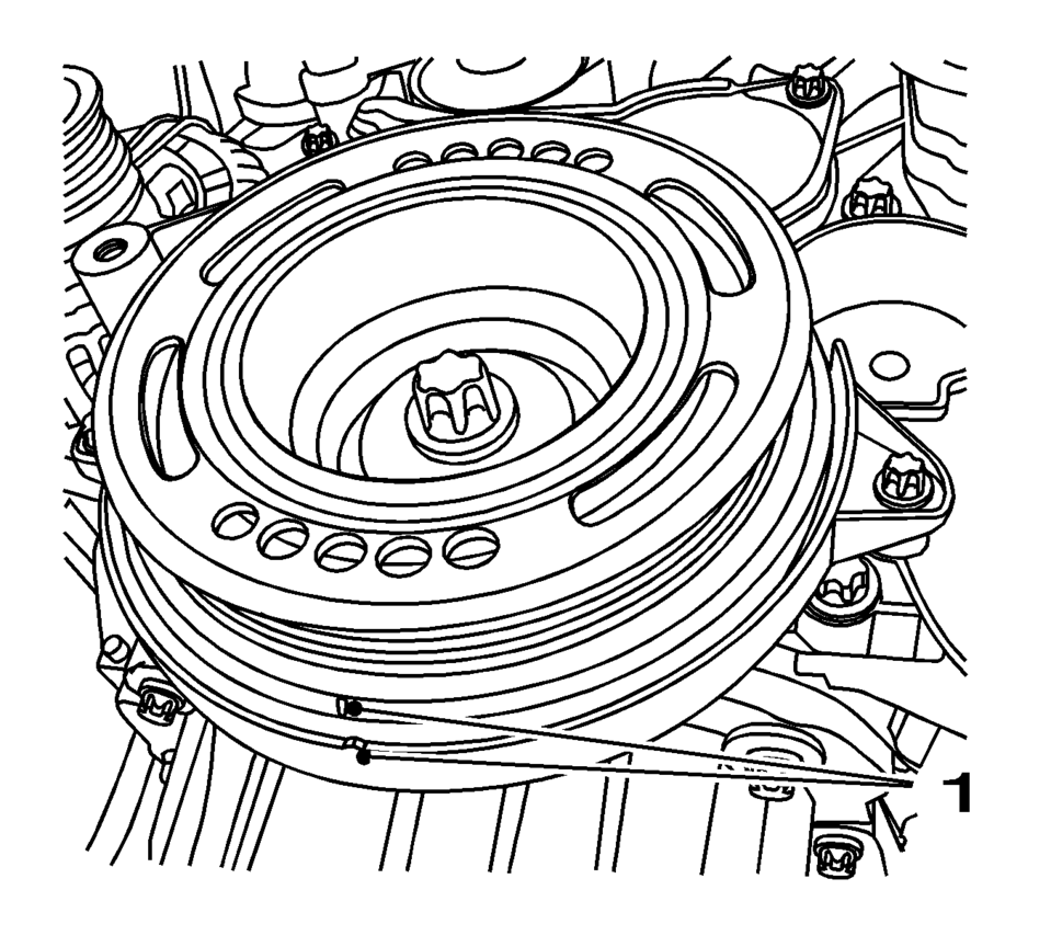
- Set the crankshaft balancer in the direction of the engine rotation to "1st cylinder TDC" (mark 1).
- Remove the camshaft cover. Refer to Camshaft Cover Removal.
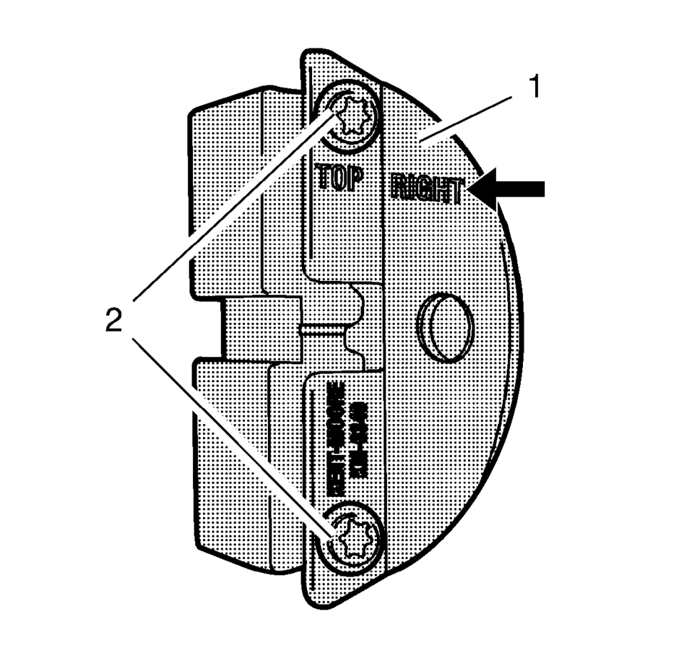
- Prepare the right half of the EN-6340 locking tool .
- Remove the 2 bolts (2).
- Remove the front panel (1) from the EN-6340 locking tool -right.
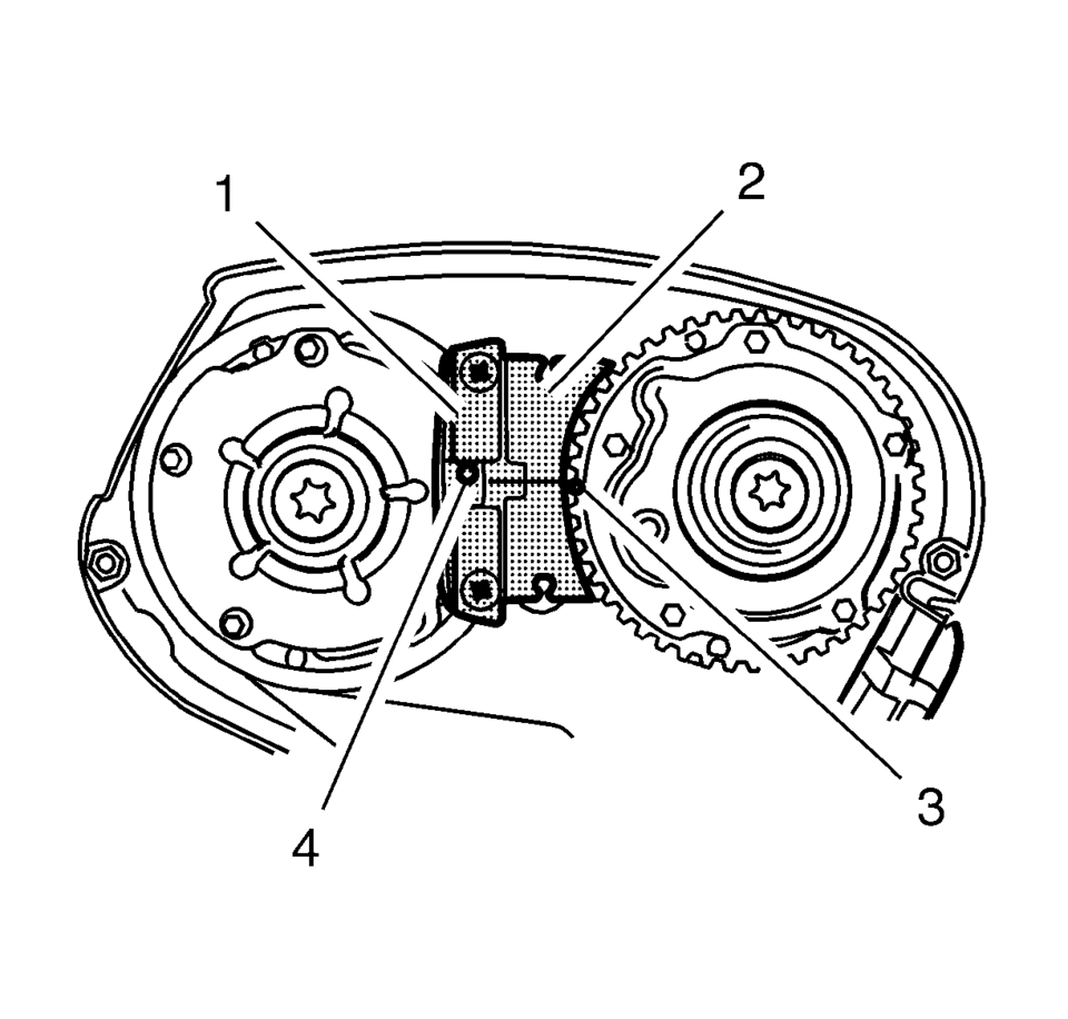
- The spot type marking (4) on the intake camshaft position actuator adjuster does not correspond to the groove of the EN-6340 locking tool - left (1) during this process, but must be somewhat above.
- The spot type marking (3) on the exhaust camshaft position actuator adjuster must correspond to the groove on EN-6340 locking tool - right (2).
- Insert the EN-6340 locking tool - left (1) and the EN-6340 locking tool - right (2) in the camshaft position actuator adjuster.
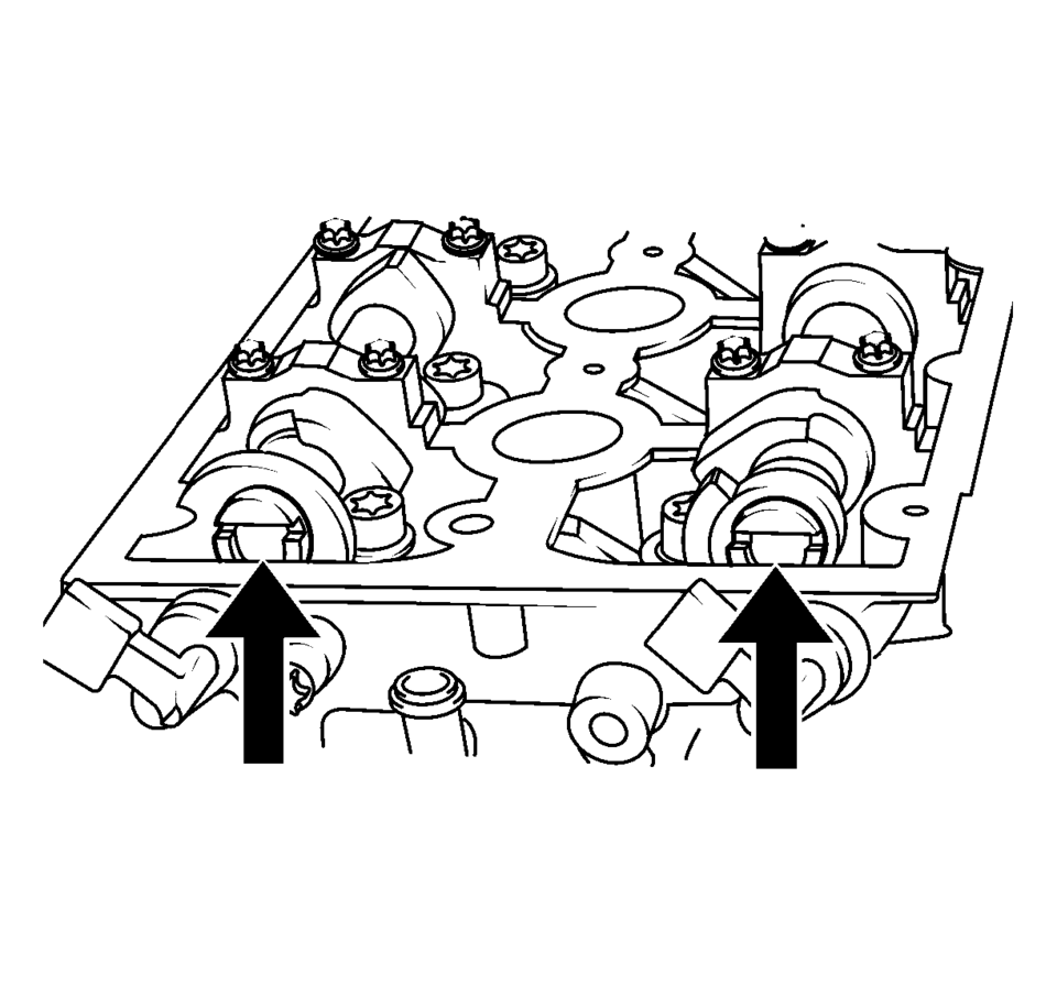
- Align the camshafts horizontally by the hexagon (arrows) until the EN-6628-A locking tool can be inserted in both camshafts.
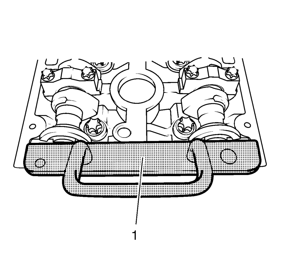
- Insert the EN-6628-A locking tool (1) into the camshafts.
Note:
The right half of the EN-6340 locking tool can be recognized by the lettering “right?E arrow, on the tool.
Note:
Note:
If the EN-6628-A locking tool cannot be inserted, the timing must be set.
- Installation Procedure
-
- Remove the EN-6628-A locking tool .
- Remove the EN-6340 locking tool .
- Install the camshaft cover. Refer to Camshaft Cover Installation.
- Install the timing belt upper front cover. Refer to Timing Belt Upper Front Cover Installation.
 Timing Belt Center Front Cover Replacement
Timing Belt Center Front Cover Replacement
Callout
Component Name
Preliminary Procedure
Remove the timing belt upper front cover. R ...
 Timing Belt Installation
Special Tools
EN-6333 Locking Pin
EN-6340 Locking Tool
For equivalent regional tools, refer to Special Tools.
Note: The timing belt drive gear and oil pump housing must align.
...
Other materials:
Radio Reception
Frequency interference and static can occur during normal radio reception if
items such as cell phone chargers, vehicle convenience accessories, and external
electronic devices are plugged into the accessory power outlet. If there is interference
or static, unplug the item from the accessory p ...
Intake Manifold Assemble (1.8L LUW and LWE)
Install the 4 NEW multiport fuel injector seals (4).
Install the multiport fuel injection fuel rail (2) and the fuel injectors (3)
to the intake manifold (5).
Caution: Refer to Fastener Caution.
Install the 2 multiport fuel in ...
Transmission General Description
The Hydra-matic 6T30/40/45/50 is a fully automatic, 6-speed, front-wheel drive,
electronic-controlled transmission. It consists primarily of a 4-element torque
converter, a compound planetary gear set, friction and mechanical clutch assemblies,
and a hydraulic pressurization and control system ...

0.0062