Chevrolet Sonic Repair Manual: Timing Belt Installation
Special Tools
- EN-6333 Locking Pin
- EN-6340 Locking Tool
For equivalent regional tools, refer to Special Tools.
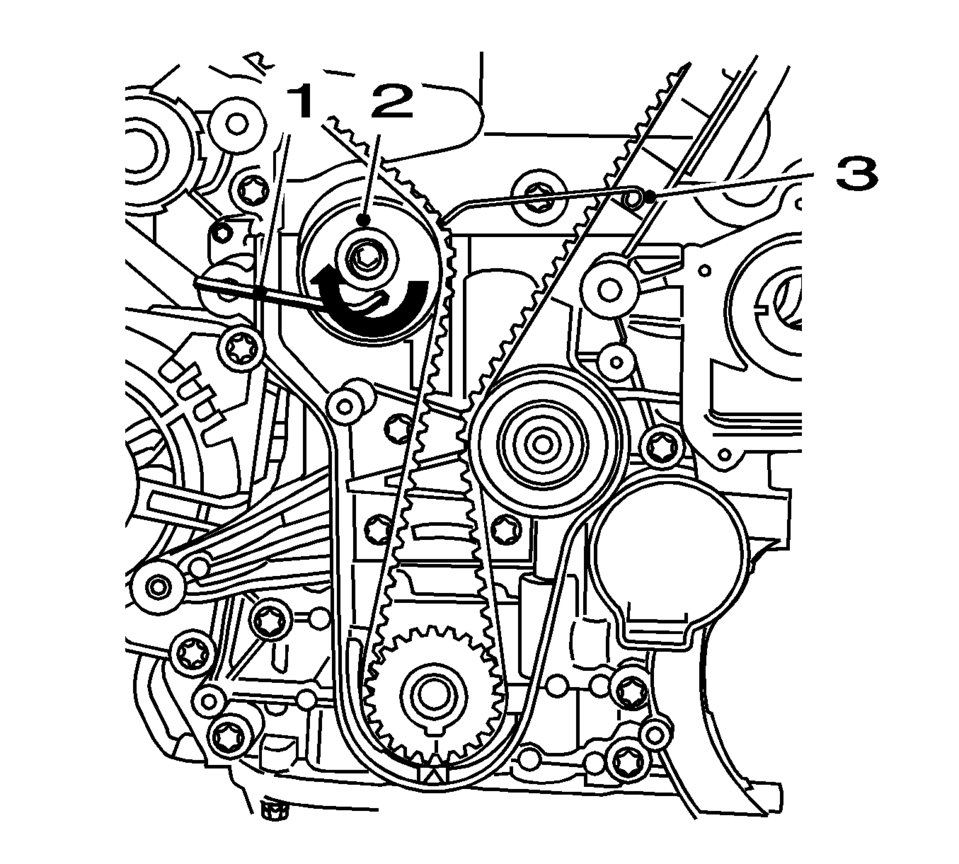
- Turn the crankshaft in the direction of engine rotation, by the crankshaft balancer bolt, to cylinder 1 TDC of combustion stroke.
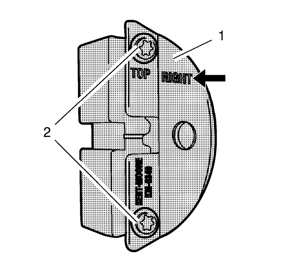
- Prepare the right half of the EN-6340 locking tool .
- Remove the 2 bolts (2).
- Detach the front panel (1) from the EN-6340 locking tool - right.
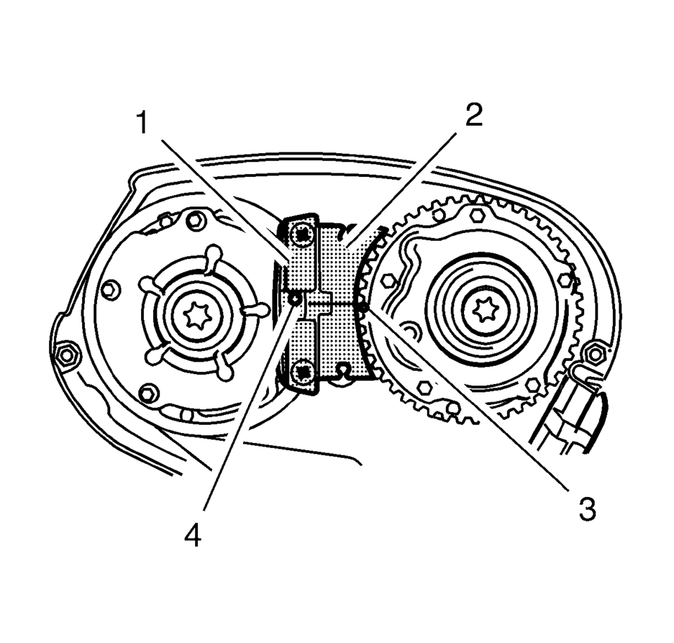
- The spot type marking (4) on the intake camshaft adjuster does not correspond to the groove of the EN-6340 locking tool - left (1) during this process, but must be somewhat above.
- The spot type marking (3) on the exhaust camshaft adjuster must correspond to the groove on EN-6340 locking tool - right (2).
- Insert the EN-6340 locking tool - left (1) and the EN-6340 locking tool - right (2) in the camshaft adjuster.
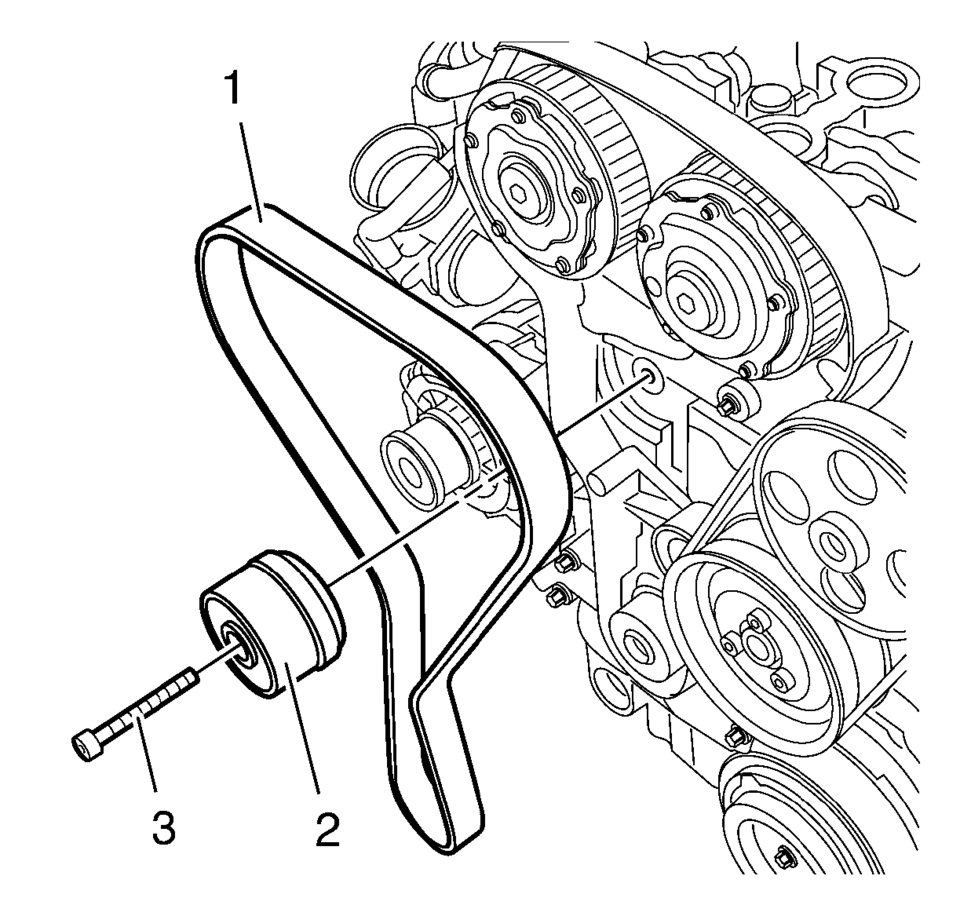
- Insert the timing belt (1).
- Apply tension to the timing belt tensioner (2) in the direction of the arrow, using an Allen key (1).
- Remove the EN-6333 locking pin (3).
- Release tension on timing belt tensioner.
- Remove the EN-6340 locking tool .
- Check position of the camshaft sprocket.
- Turn crankshaft 720° in the direction of engine rotation by the crankshaft balancer bolt.
- Insert EN-6340 locking tool into camshaft sprockets.
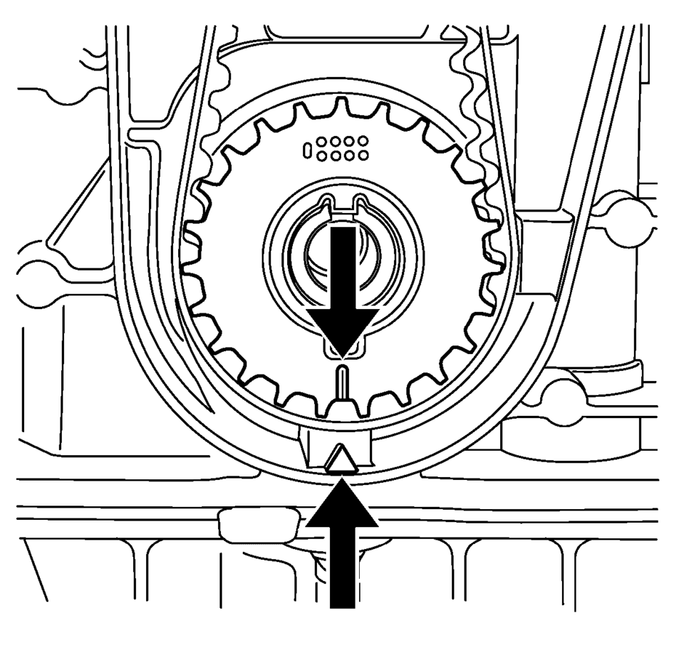
- Check the crankshaft position.
Note:
The timing belt drive gear and oil pump housing must align.
Note:
The right half of the EN-6340 locking tool can be recognized by the lettering right, arrow, on the tool.
Note:
Note:
Observe direction of rotation.
Note:
The timing belt tensioner moves automatically to the correct position.
Note:
Note the marking on the camshaft sprocket.
Note:
The timing belt drive gear and oil pump housing must align.
 Timing Belt Inspection
Special Tools
EN-6340 Locking Tool
EN-6628-A Locking Tool
For equivalent regional tools, refer to Special Tools.
Removal Procedure
Remove the timing belt upper front cover. Ref ...
 Timing Belt Lower Front Cover Installation
Caution: Refer to Fastener Caution.
Install the timing belt cover (1) and tighten the 4 timing belt lower front cover
bolts (2) to 6 Y (53 lb in ...
Other materials:
Instrument Panel Lower Airbag Replacement - Driver Side
Instrument Panel Lower Airbag Replacement - Driver Side
Callout
Component Name
Warning: Refer to SIR Inflator Module Handling and Storage
Warning.
Warning: Refer to SIR Warning.
Preliminary Procedure
...
Evaporative Emission System Hose/Pipe Replacement
Removal Procedure
Disconnect the evaporative emission pipe (1). Refer to Plastic Collar
Quick Connect Fitting Service.
Remove the plastic retainer (1) and disconnect the evaporative emission
pipe (2).
Lift and support t ...
Intelligent Key operation
Example
Example
The Nissan Armada Intelligent Key system allows seamless locking and unlocking
of doors without removing the key from your pocket or bag, enhancing both convenience
and everyday usability.
When carrying the Nissan Armada Intelligent Key within the operating range, you ...

0.0076