Chevrolet Sonic Repair Manual: Transmission Case Assemble (Gen 1)
Special Tools
- 3-9506289 Universal Adapter
- J-840733 Driver
- R-0007758 Holding Fixture
- R-0007761 Universal Handle
- R-0007770 Holding Fixture Adapter Plates
- T-9804669 Seal Installer
- T-0307000 Extractor and Driver Fixture
For equivalent regional tools, refer to Special Tools.
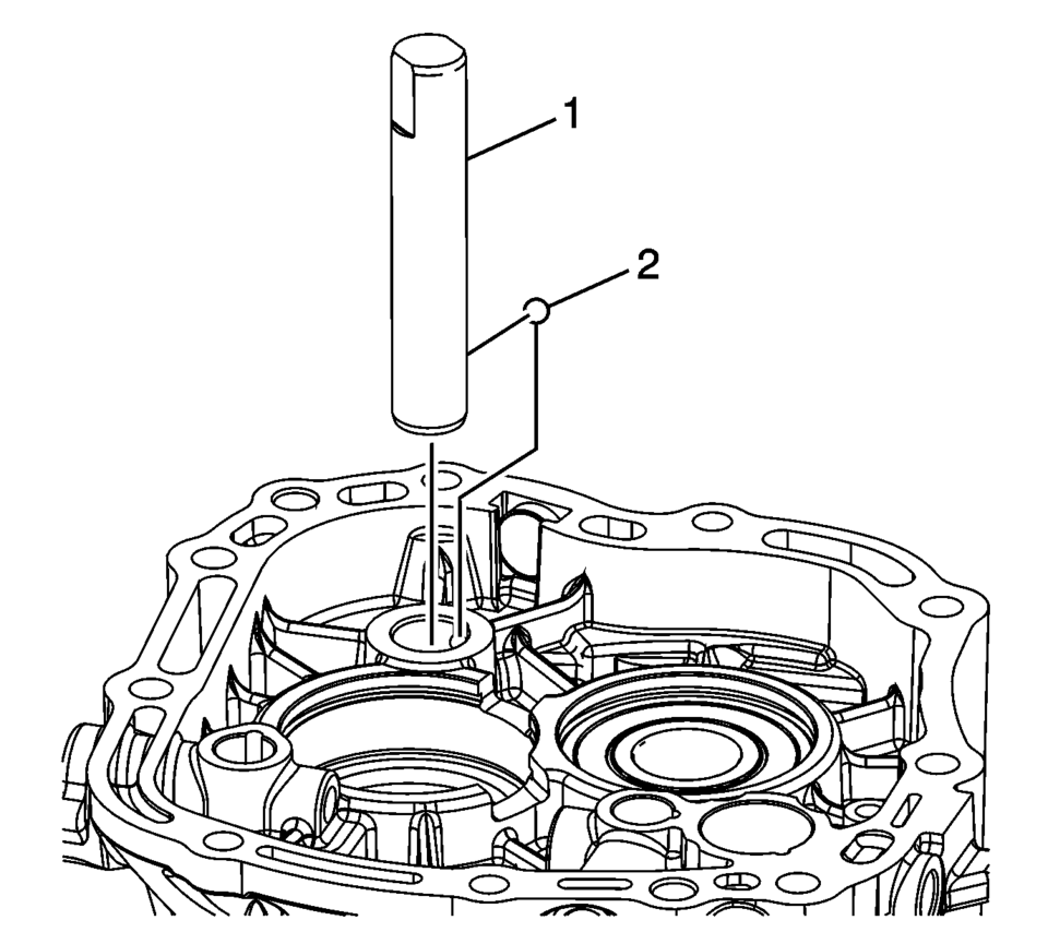
- Install the reverse idler gear shaft retaining ball (2).
- Install the reverse idler gear shaft (1).
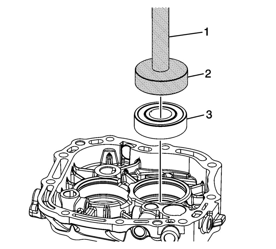
- Using T-9804669 seal installer (2) and R-0007761 handle (1), install the mainshaft bearing (3) into the case.
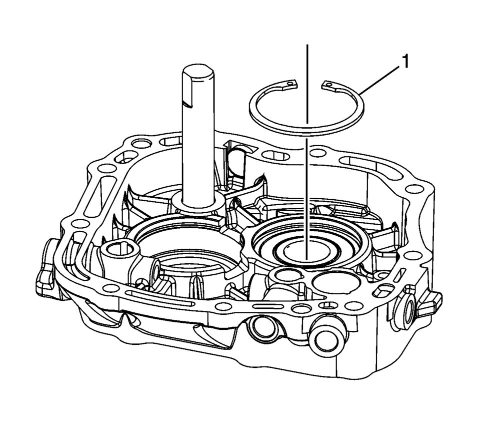
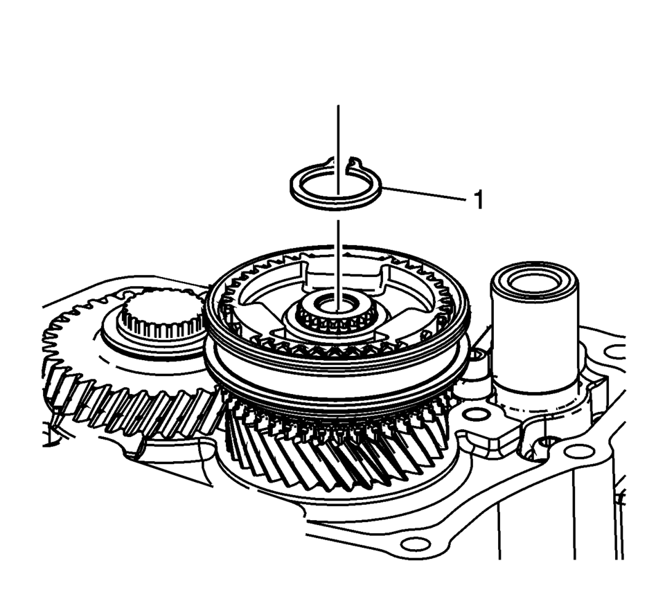
- Install the mainshaft bearing retaining ring (1).
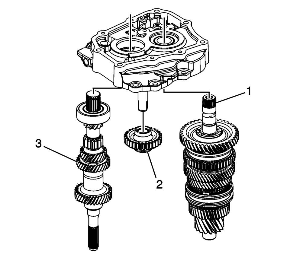
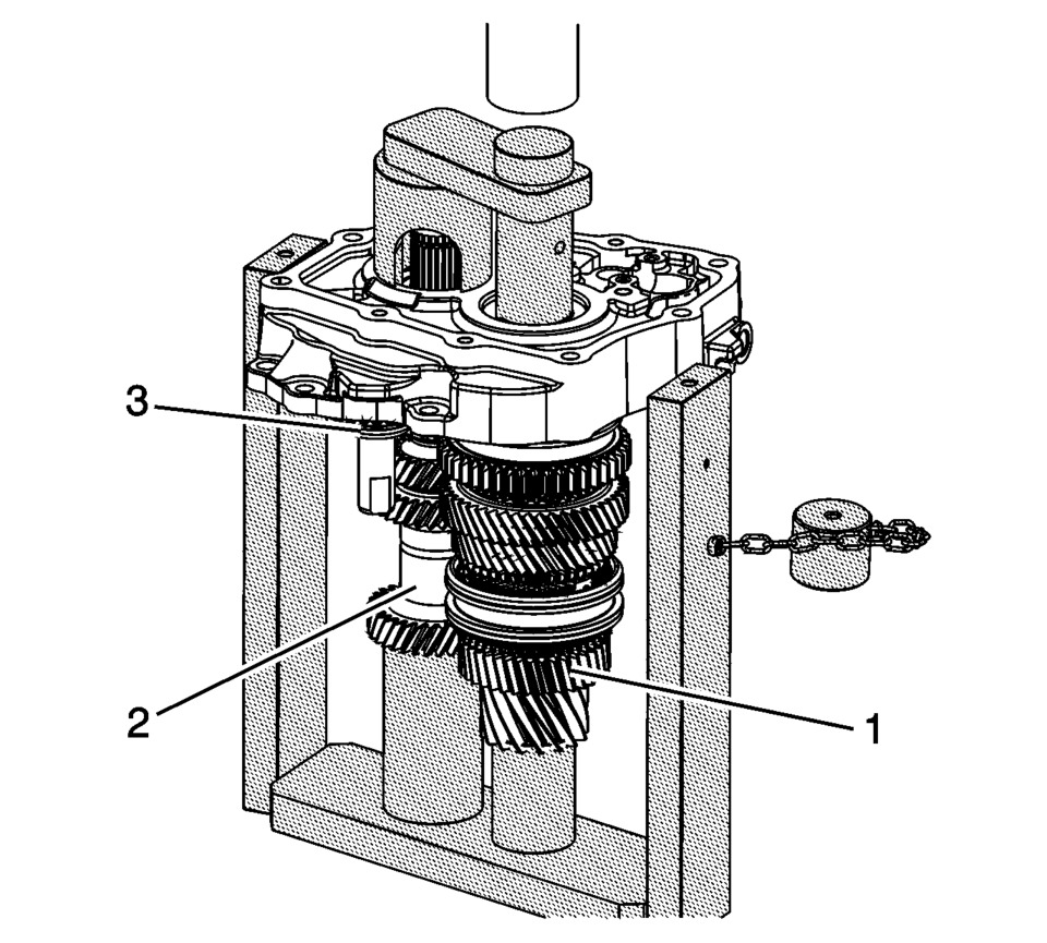
- Install the input shaft (3), reverse idler gear (2) and mainshaft (1) onto the T-0307000 driver fixture with top plate removed.
- Guide the shafts (1?) into the bores, and support the reverse idler gear (3) while pressing into the case.
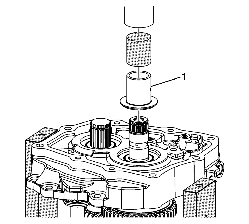
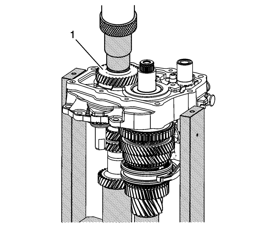
- Using the T-0307000 driver fixture , press the 5th gear bearing race (1) onto the mainshaft.
- Install the case and shafts assembly onto the R-0007770 adapter plates (1) and R-0007758 holding fixture (2).
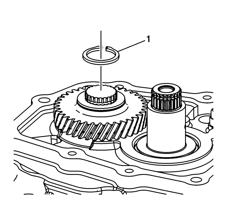
- Install the input shaft bearing retaining ring (1).
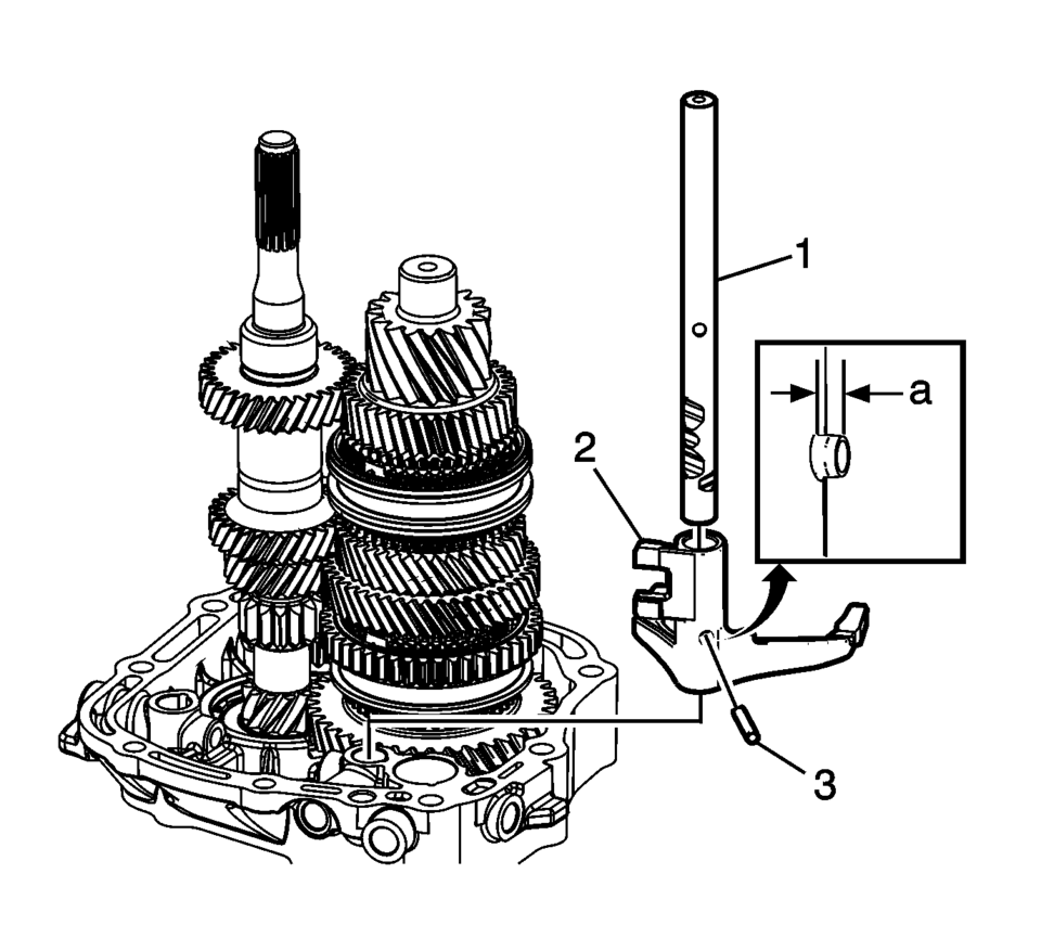
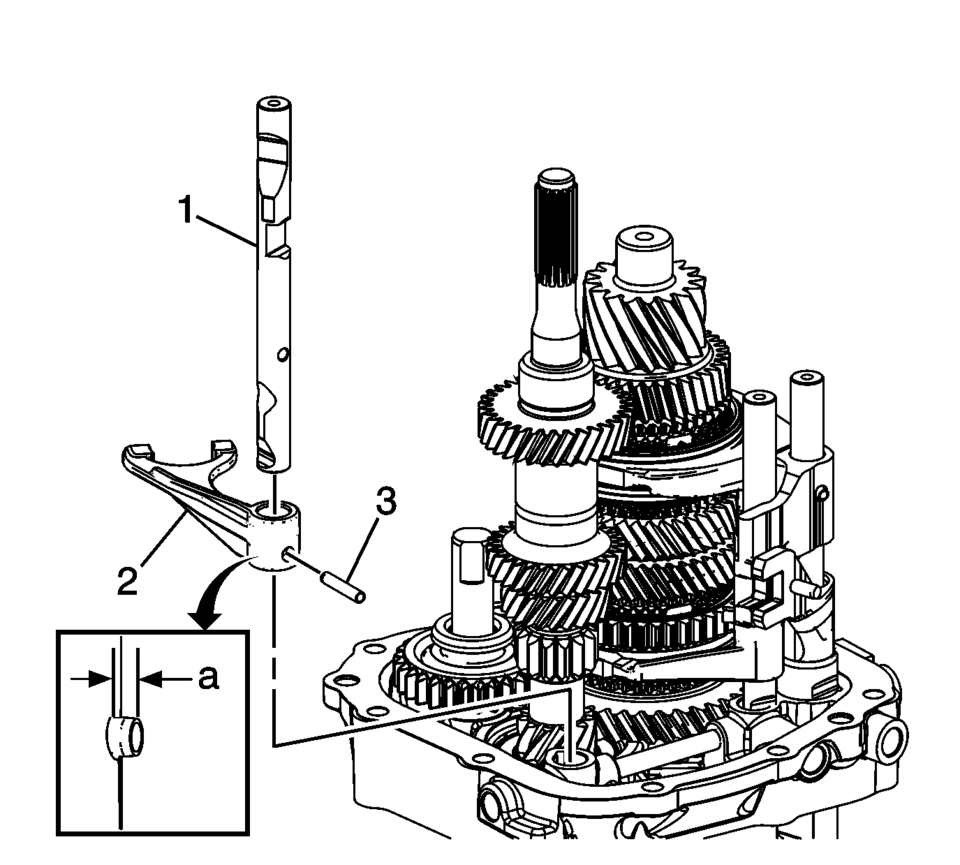
- Install the 1st and 2nd shift fork (2).
- Install the 1st and 2nd shift shaft (1).
- Install the 1st and 2nd shift fork pin (3) to the dimension ??depth of
2 mm (0.80 in)
.
- Install the gearshift rod (1) into the transmission case.
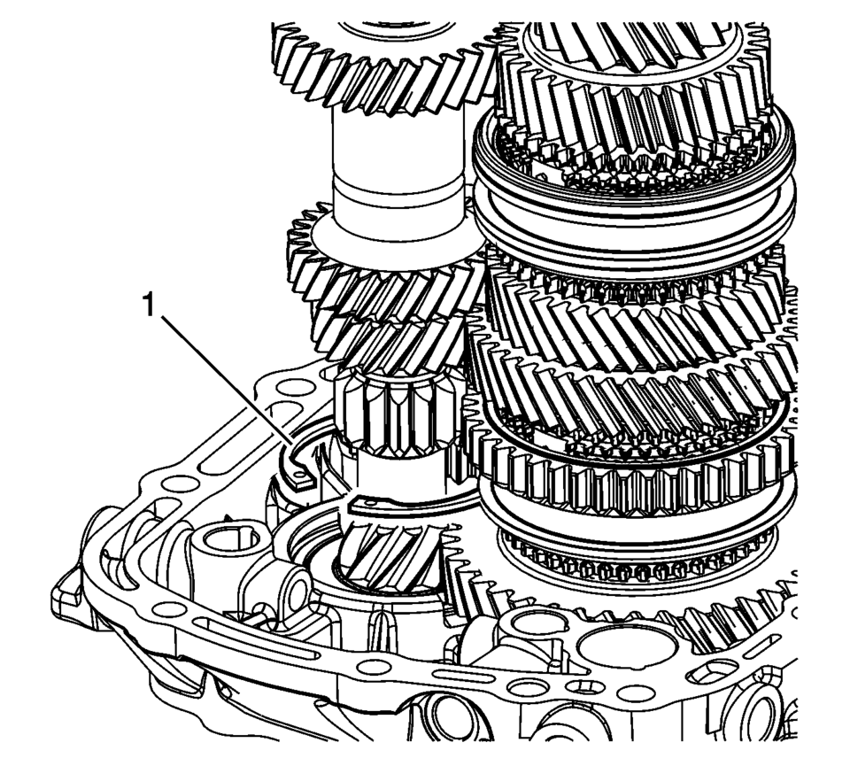
- Install the 5th shift blocking guide (1) into the transmission case.
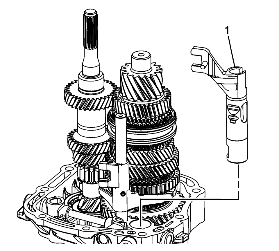
- Install the 3rd and 4th shift fork (2).
- Install the 3rd and 4th shift shaft (1).
- Install the 3rd and 4th shift fork pin (3) to the dimension ??depth of
2 mm (0.80 in)
.
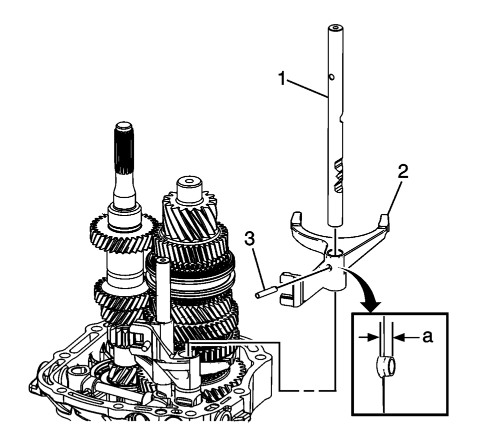
- Install the reverse shift fork (2).
- Install the reverse shift shaft (1).
- Install the reverse shift fork pin (3) to the dimension ??depth of
2 mm (0.80 in)
.
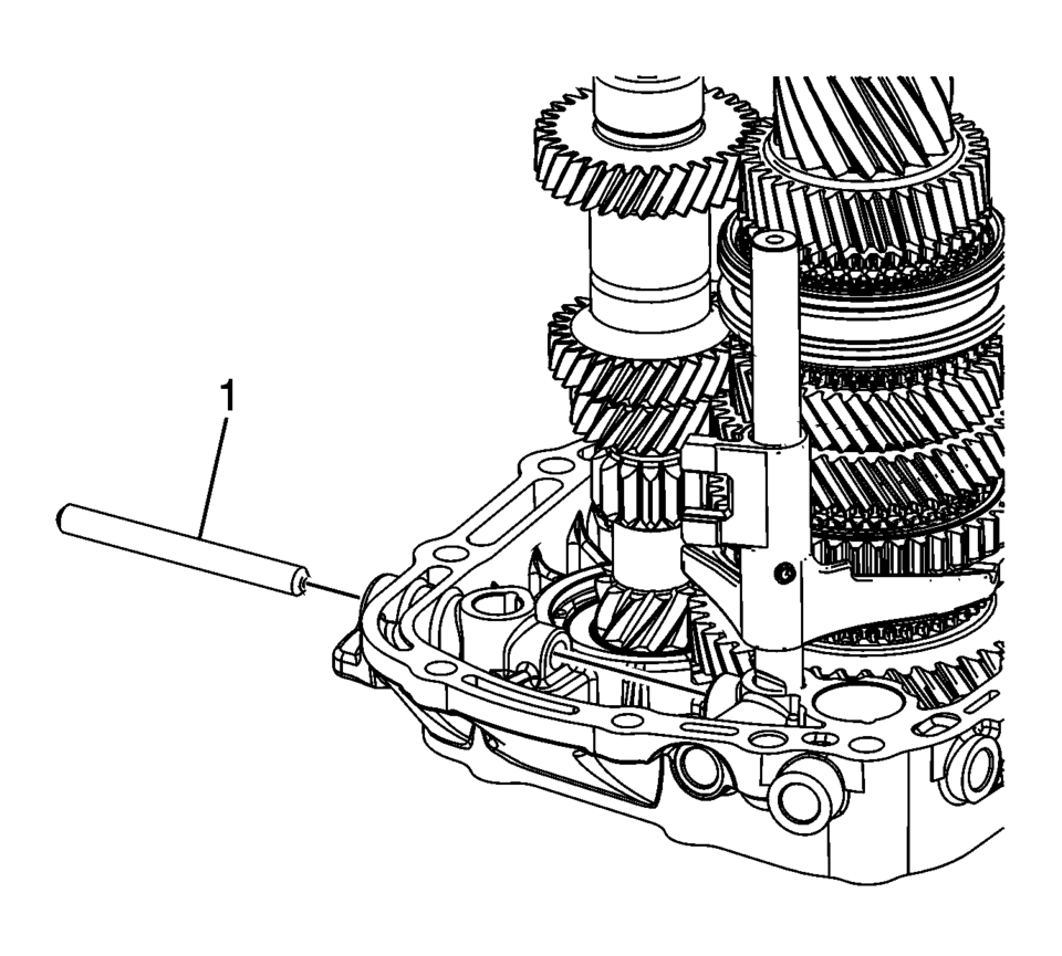
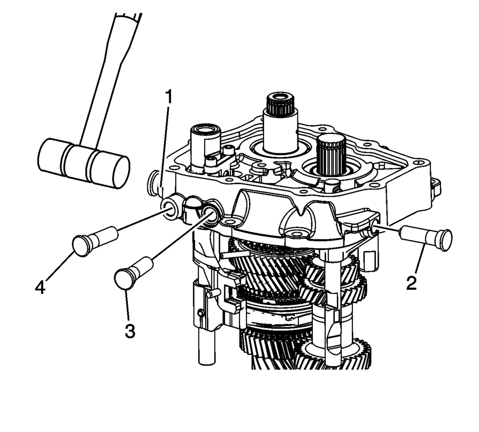
- Using a plastic hammer or equivalent install the 4 shift shaft detent sleeves (1?) into the transmission case until they stop.
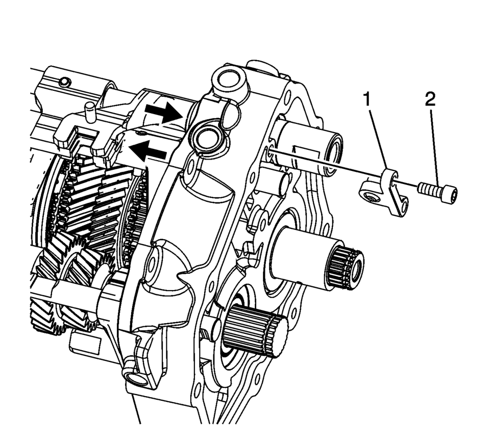
- Install the shift shaft interlock pin connector (1).
- Using thread locking compound install the shift shaft interlock pin connector
bolts (2) and tighten to 7 Y (62 lb in)
.
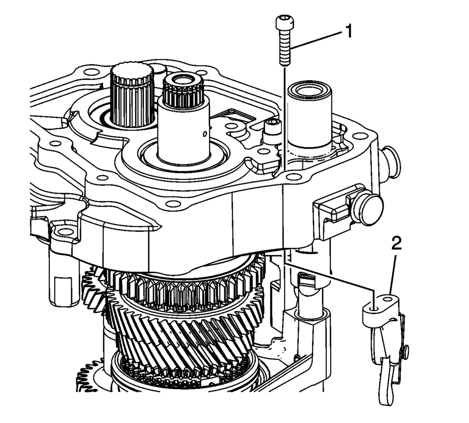
- Install the parking pawl (2).
- Using thread locking compound install the parking pawl retaining bolts (1)
and tighten to 7 Y (62 lb in)
.
- Remove case and shafts assembly from R-0007770 adapter plates and install onto T-0307000 driver fixture .
- Using J-840733 driver , press the 5th gear, driving (1) onto the input shaft.
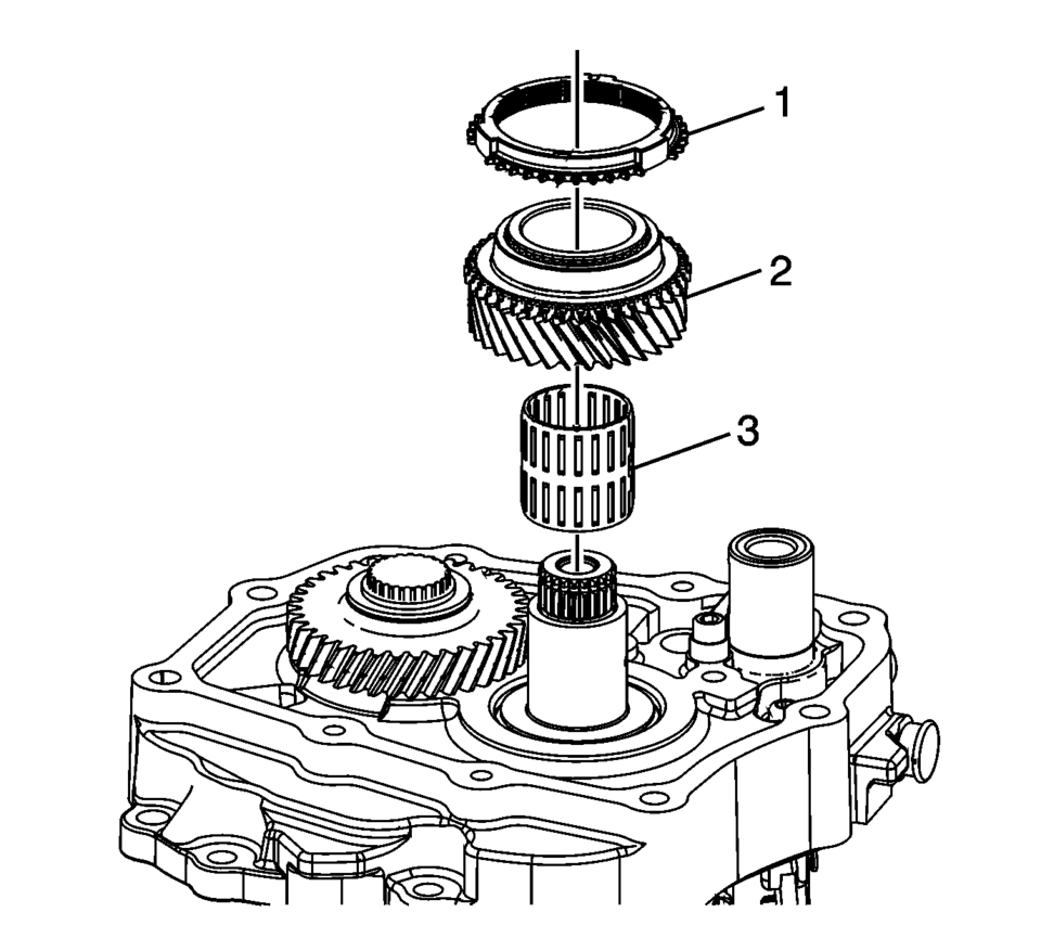
- Install a NEW 5th gear retaining ring (1).
- Install the 5th gear bearing assembly (3).
- Install the 5th gear assembly, driven (2).
- Install the 5th gear blocking ring (1).
- Ensure that the synchronizer assembly (1) is functioning properly, refer to Synchronizers Cleaning and Inspection and Synchronizers Assemble.
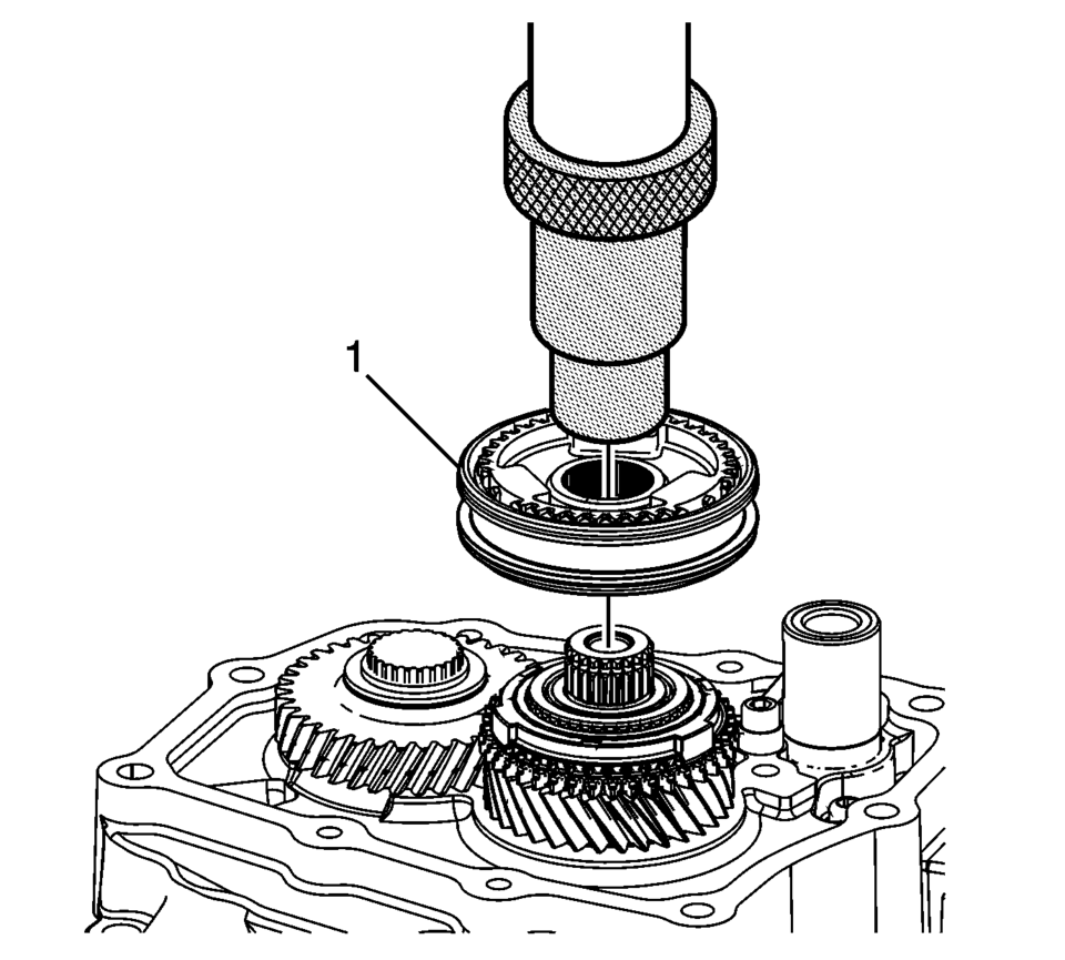
- Using the J-840733 driver and a press, install the 5th gear synchronizer assembly (1).
- Install the 5th gear sychronizing hub retaining ring (1).
- Remove the case and shafts assembly from the T-0307000 driver fixture .
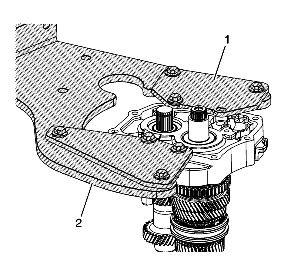
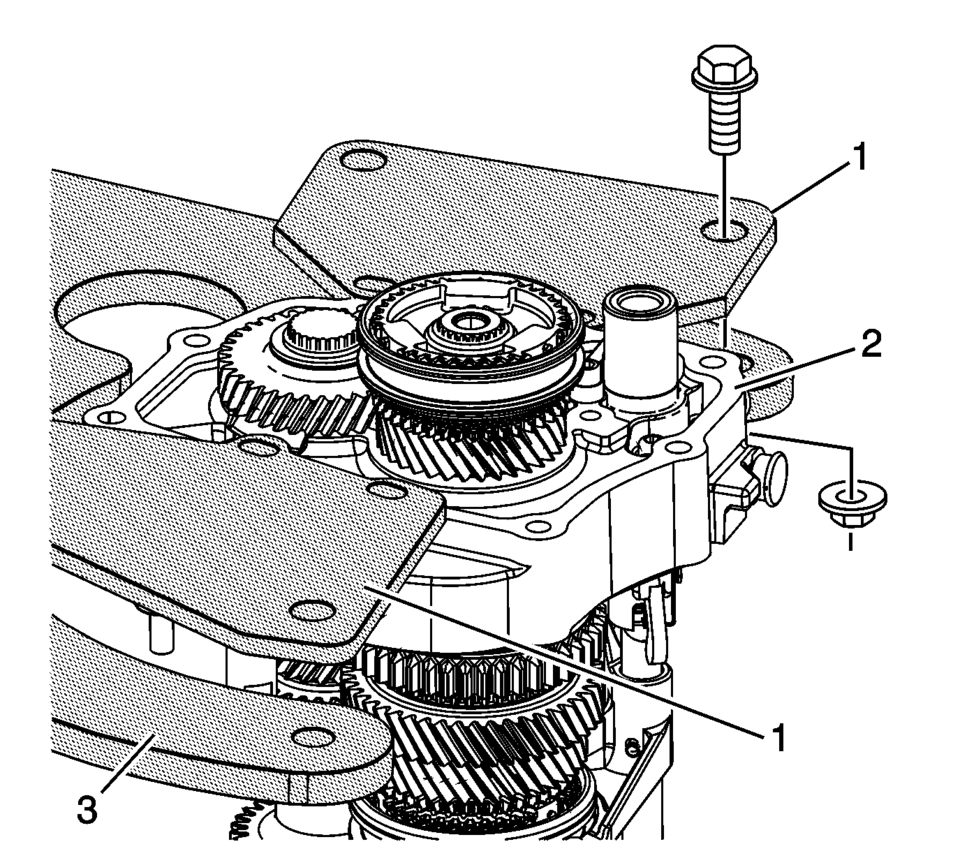
- Install R-0007770 adapter plates (1) onto case (2) and then attach to R-0007758 holding fixture (3).
- Install the 5th shift fork shoes (3).
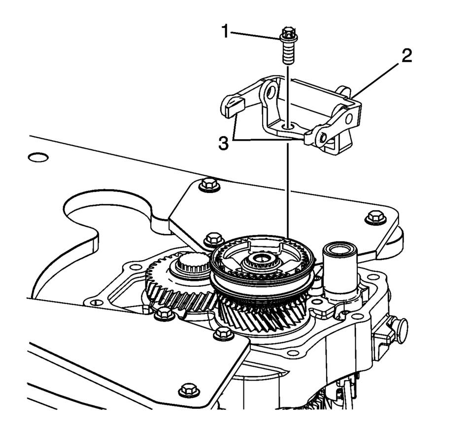
- Install the 5th shift fork bracket assembly (2).
- Using thread locking compound install the 5th shift fork bracket bolts (1)
and tighten to 22 Y (16 lb ft)
.
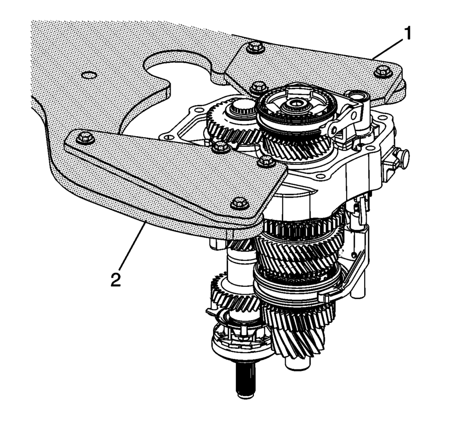
- Remove the transmission case, from the R-0007770 adapter plates (1) the R-0007758 holding fixture and 3-9506289 adapter .
Note:
Engage the shift shafts into 3rd gear and 5th gear as indicated with arrows to install the interlock pin connector.
Note:
Move shift forks into neutral position.
Caution:
Refer to Fastener Caution.
 Transmission Assemble (Gen 2)
Special Tools
3-9506289 Universal Adapter
R-0007758 Holding Fixture
S-9407197 Differential Rotating Tool
S-9407198 Differential Bearing Race Wrench
For equivalent regional tools, refer ...
 Transmission Case Assemble (Gen 2)
Special Tools
3-9506289 Universal Adapter
J-840733 Driver
R-0007758 Holding Fixture
R-0007761 Universal Handle
R-0007770 Holding Fixture Adapter Plates
T-9804669 Seal Installer
T-0 ...
Other materials:
Master Cylinder Reservoir Filling
Warning: Refer to Brake Fluid Irritant Warning.
Caution: Refer to Brake Fluid Effects on Paint and Electrical Components
Caution.
Visually inspect the brake fluid level through the brake master cylinder
reservoir.
If the brake fluid level is at or below the half-full point ...
Secondary Air Injection Pump Installation
Install the secondary air injection pump (1).
Loosely install the secondary air injection pump nut (2) and the 2 secondary
air injection pump bolts (4).
Caution: Refer to Fastener Caution.
Tighten the secondary air injection pump nut (2) an ...
Maximum load limits
Maximum trailer loads
Never exceed the maximum allowable trailer load specified in the "Towing load/specification"
section. The total trailer load includes both the trailer itself and any cargo it
carries.
When towing loads of 3,500 lbs (1,587 kg) or more with your Nissan
Armad ...

0.0074