Chevrolet Sonic Repair Manual: Transmission Case Assemble (Gen 2)
Special Tools
- 3-9506289 Universal Adapter
- J-840733 Driver
- R-0007758 Holding Fixture
- R-0007761 Universal Handle
- R-0007770 Holding Fixture Adapter Plates
- T-9804669 Seal Installer
- T-0307000 Extractor and Driver Fixture
For equivalent regional tools, refer to Special Tools.
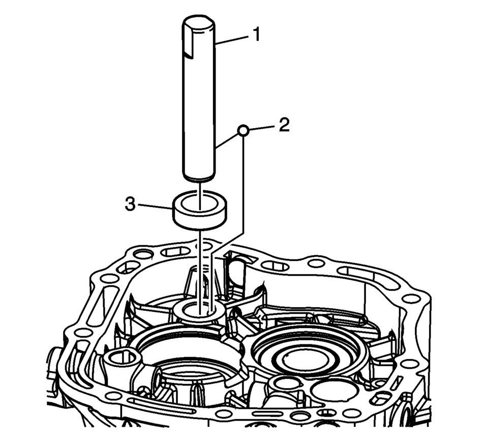
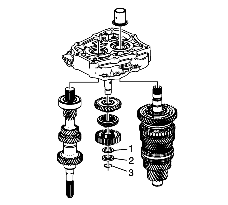
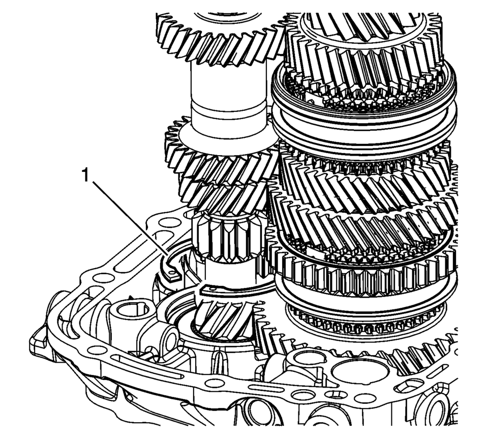
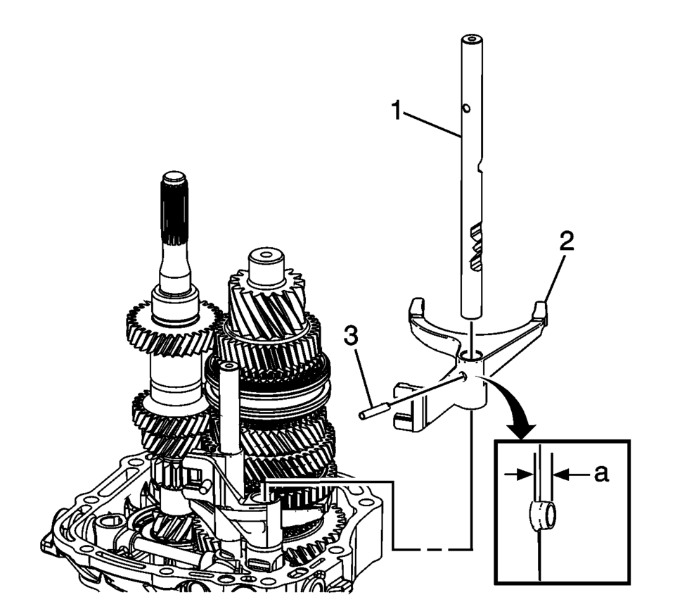
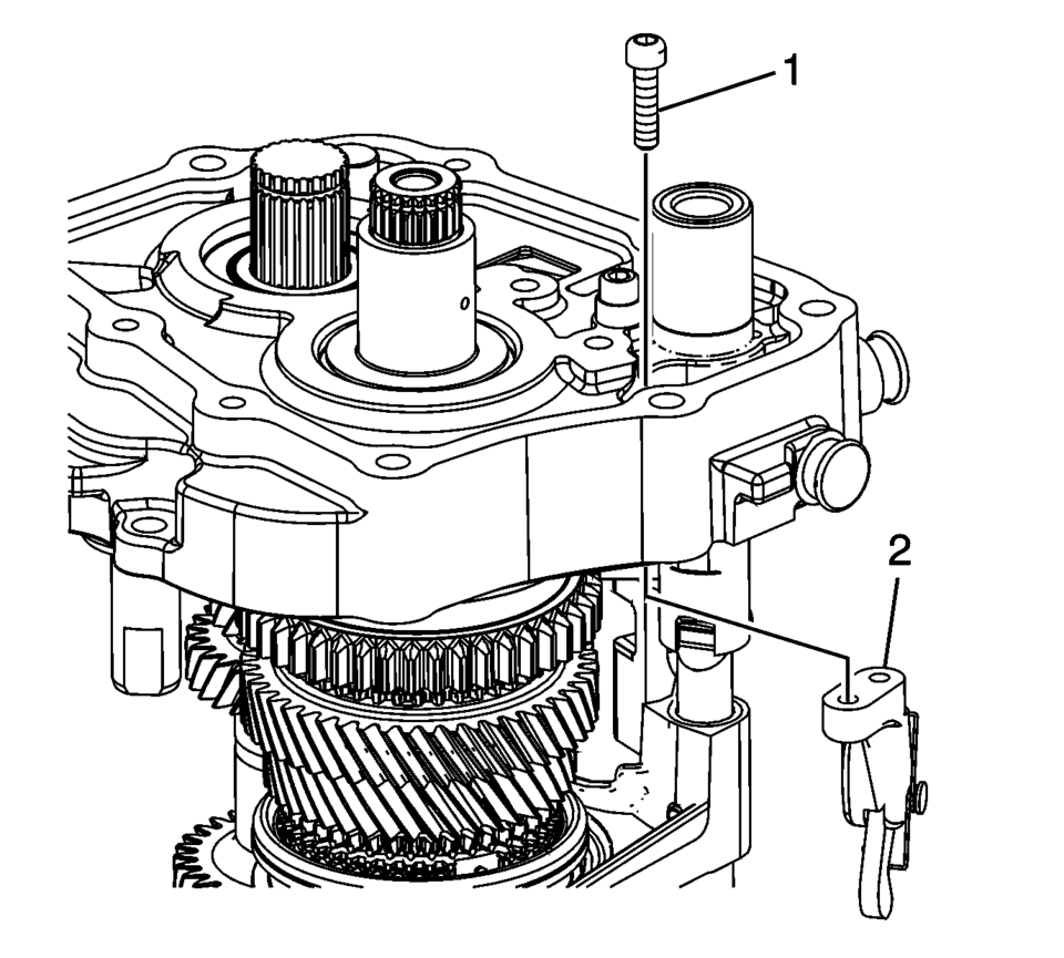
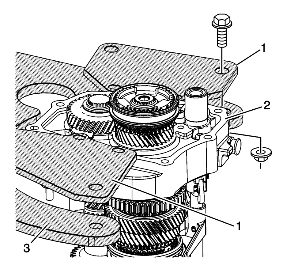
- Install the reverse helical gear washer (3) onto the reverse idler gear shaft.
- Install the reverse idler gear shaft retaining ball (2).
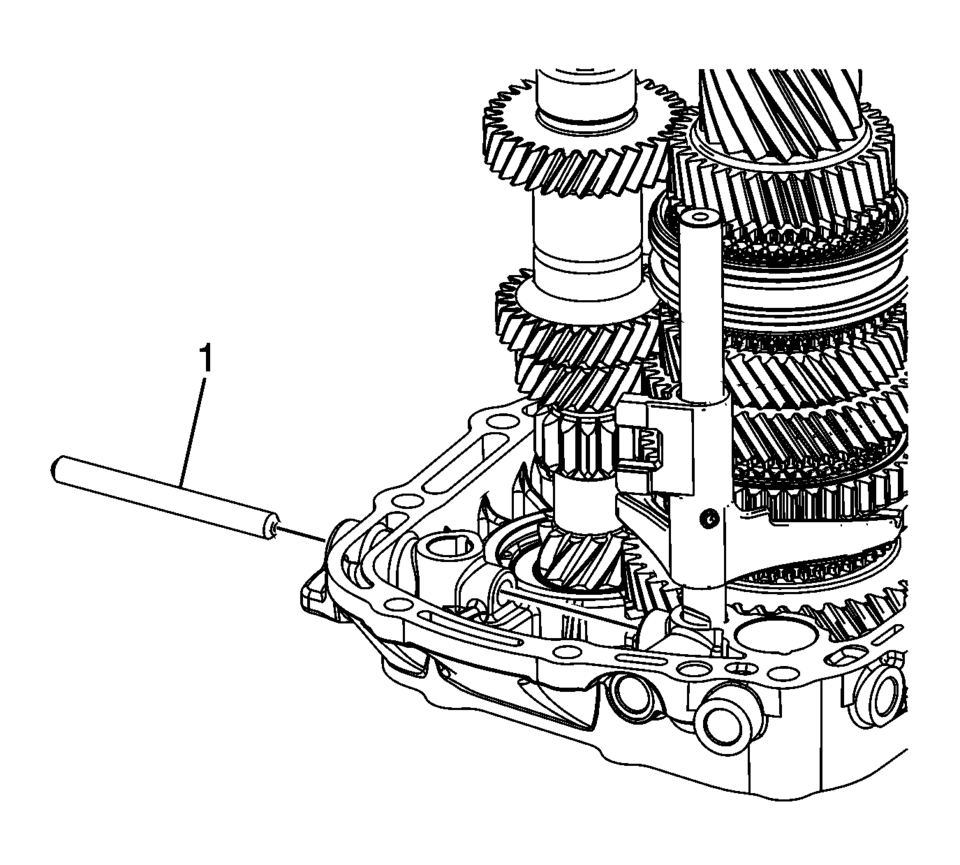
- Install the reverse idler gear shaft (1).
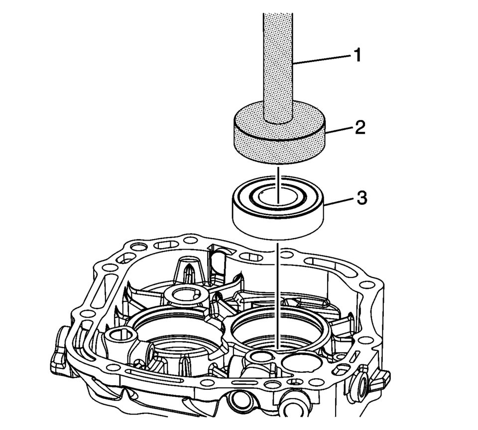
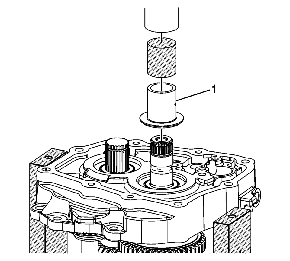
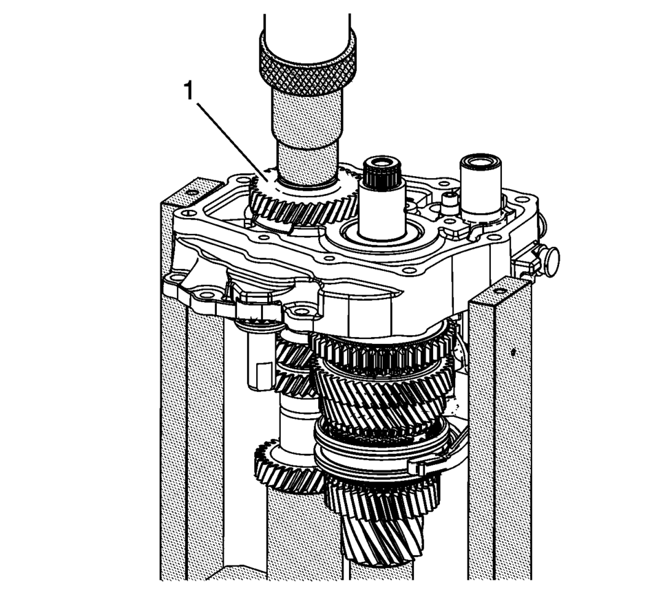
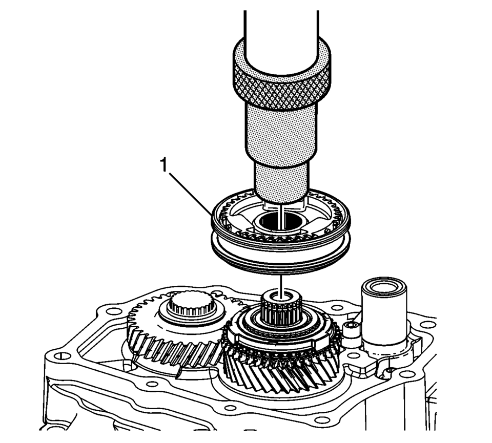
- Using T-9804669 seal installer (2) and R-0007761 handle (1), install the mainshaft bearing (3) into the case.
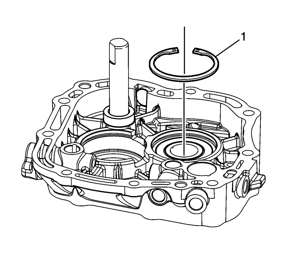
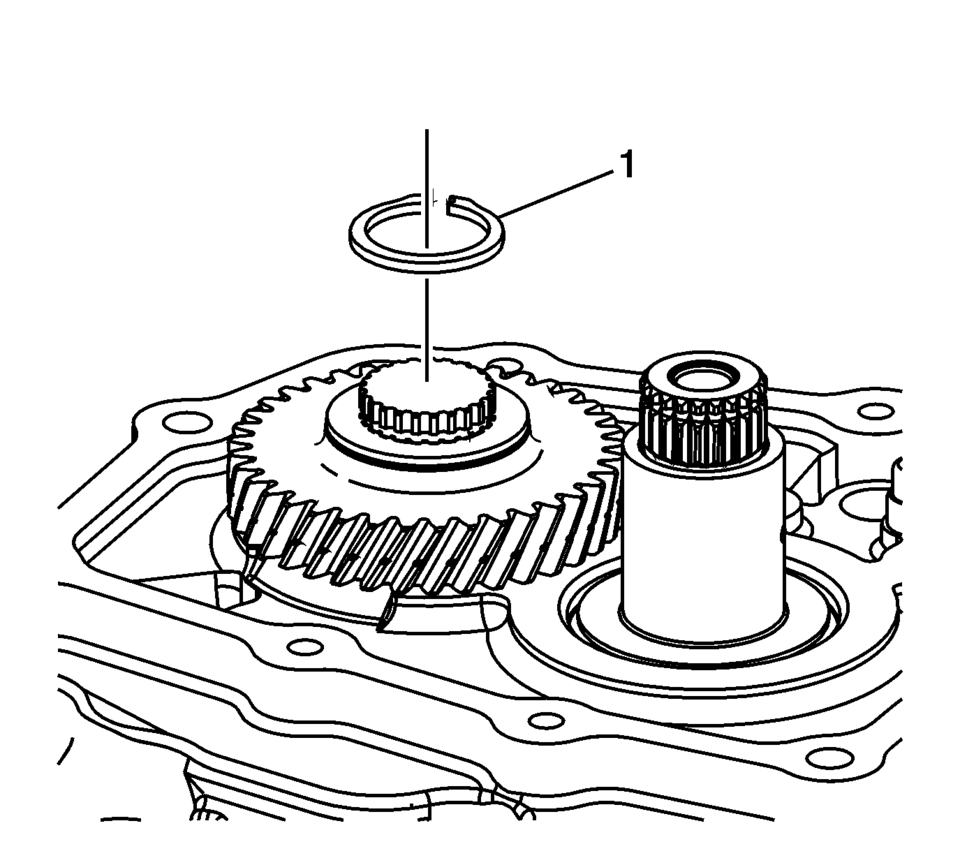
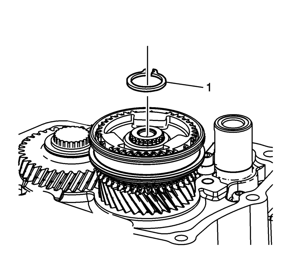
- Install the mainshaft bearing retaining ring (1).
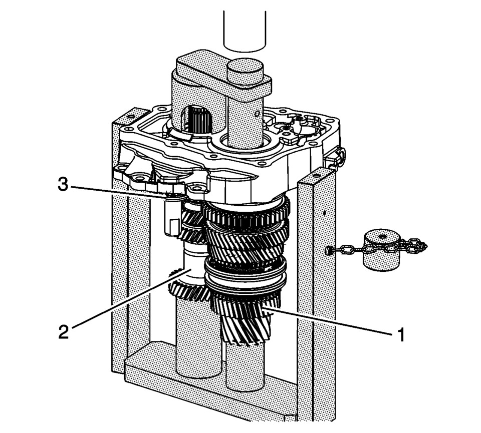
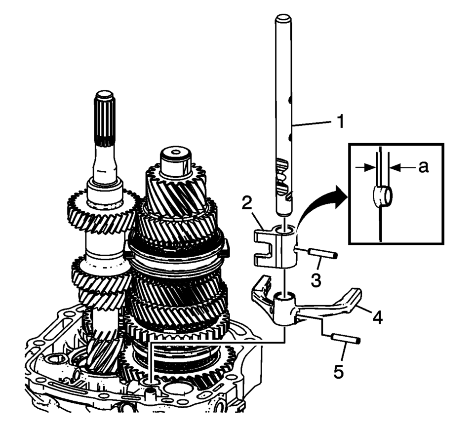
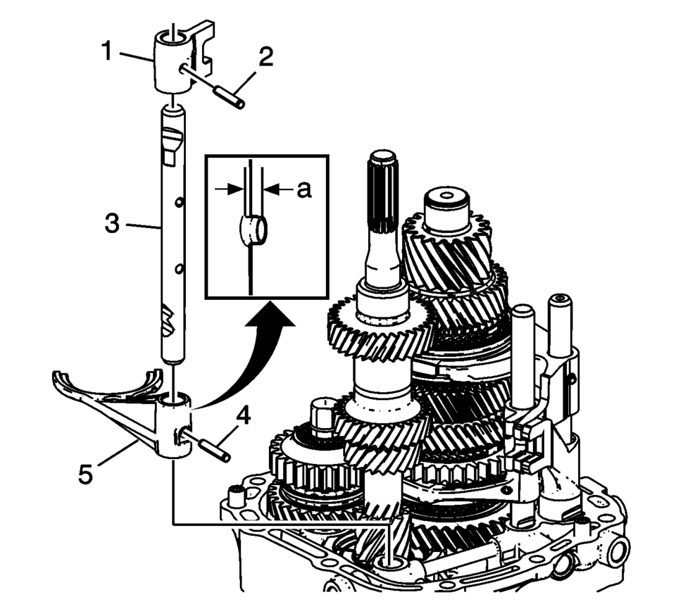
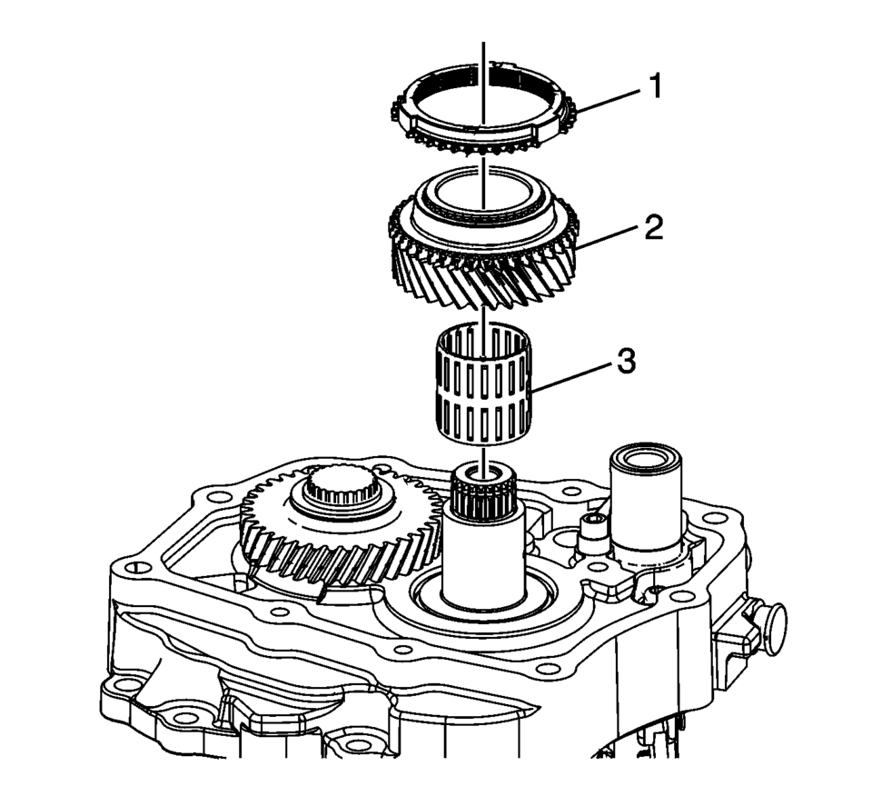
- Install the following components onto the T-0307000 driver fixture with top plate removed.
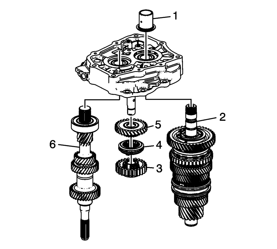
- Main shaft (2)
- Reverse helical gear (5)
- Reverse synchro assembly (4)
- Reverse spur gear (3)
- Input Shaft (6)
Note:
While pressing, pay attention to the input shaft bearing retaining ring, because it can be pressed into the first gear.
Note:
The reverse gear shaft snap ring (3) MUST be installed even if not originally equipped to prevent shifting issues caused by incorrect assembly or parts not in position.
.
.
.
.
.
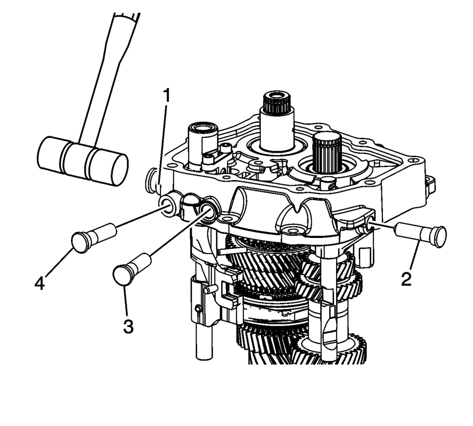
Note:
Engage the shift shafts into 2nd gear, 5th gear, and 3rd gear as indicated with arrows to install the interlock pin connector.
.
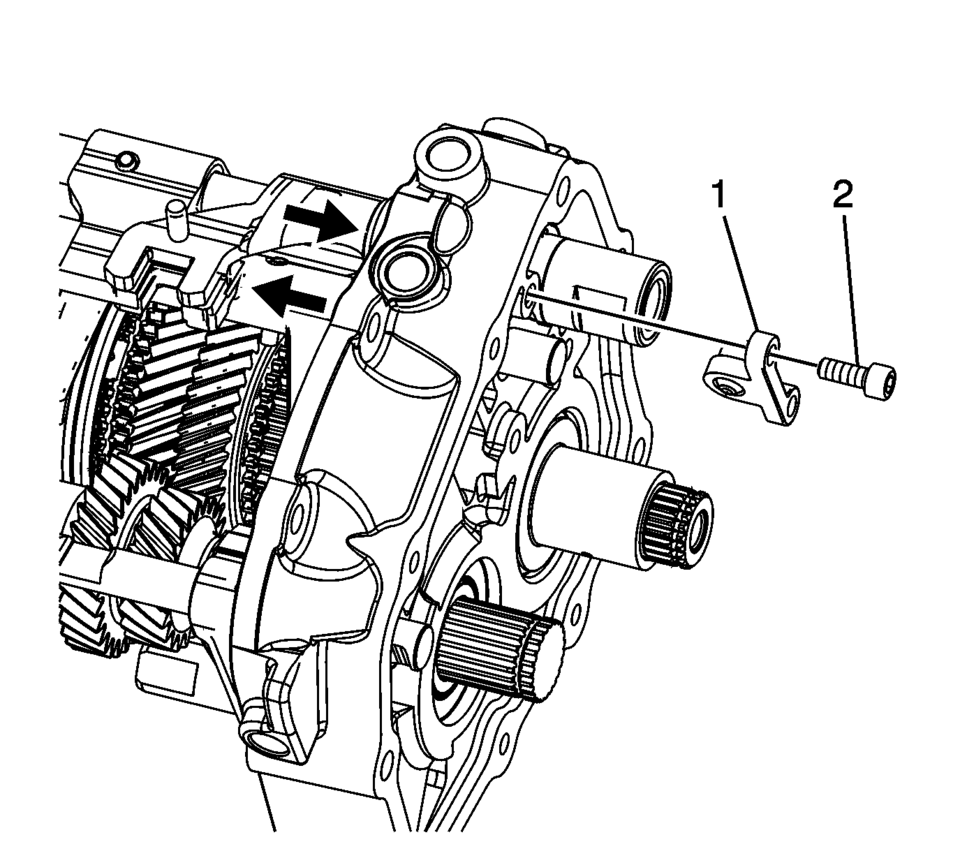
Note:
Move shift forks into neutral position.
Caution:
Refer to Fastener Caution.
.
.
 Transmission Case Assemble (Gen 1)
Special Tools
3-9506289 Universal Adapter
J-840733 Driver
R-0007758 Holding Fixture
R-0007761 Universal Handle
R-0007770 Holding Fixture Adapter Plates
T-9804669 Seal Installer
T-0 ...
 Transmission Case Disassemble (Gen 1)
Special Tools
3-9506289 Universal Adapter
J-810700 Mainshaft Bearing Remover
J-810704 Center Bar Puller
M-680770 Universal Sliding Mallet
R-0007758 Holding Fixture
R-0007770 Holding F ...
Other materials:
Radio Front Side Door Speaker Replacement
Radio Front Side Door Speaker Replacement
Callout
Component Name
Preliminary Procedure
Remove the front side door trim. Refer to Front
Side Door Trim Replacement.
1
Radio Front Side Door Speaker ...
Hub/Axle Flange and Wheel Stud Runout Inspection
Special Tools
GE-8001 Dial Indicator Set , or equivalent
Raise and support the vehicle. Refer to Lifting and Jacking the Vehicle.
Mark the location of the wheels to the wheel studs and mark the specific
vehicle position on each tire and wheel – LF, LR, RF, RR.
Remove the tire and ...
Drive and Driven Sprocket, Drive Link, and Park Pawl Installation (6T40/45/50)
Drive and Driven Sprocket, Drive Link, and Park Pawl Installation
Callout
Component Name
1
Front Differential Carrier Baffle
2
Front Differential Carrier Baffle Bolt M6 x 16& ...

0.0061