Chevrolet Sonic Repair Manual: Transmission Fluid Pump Assemble (6T40/45/50)
| Table 1: | Fluid Pump w/Valve Trains Assemble |
| Table 2: | Torque Converter Fluid Seal and Fluid Filter Assembly Assemble |
- Fluid Pump w/Valve Trains Assemble
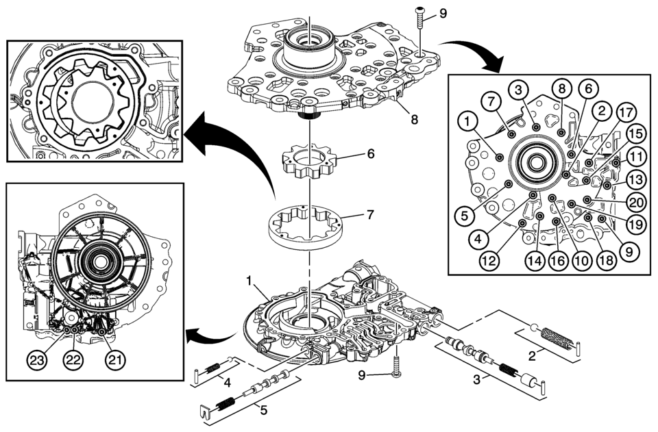
Fluid Pump w/Valve Trains Assemble Callout
Component Name
1
A/Trans Fluid Pump Body
2
Fluid Pump Blow Off Ball Valve Train
3
Pressure Regulator Valve Train
4
TCC Blow Off Ball Valve Train
5
TCC Control Valve Train
6
Fluid Pump Drive Gear
Note:
- Align ID feature dots with the driven gear as shown above.
- The chamfer on the drive gear teeth faces the pump body.
7
Fluid Pump Driven Gear
Note:
- Align ID feature dots with the drive gear as shown above, some models.
- The chamfer on the driven gear O.D. faces the pump body.
8
Fluid Pump Cover
9
Fluid Pump Cover Bolts M6 x 25 (Qty: 23)
TightenCaution:
Refer to Fastener Caution.
12 Y (106 lb in)
- Torque Converter Fluid Seal and Fluid Filter Assembly Assemble
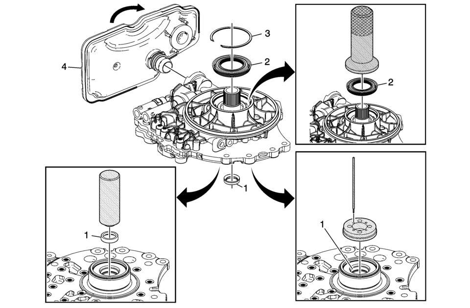
Torque Converter Fluid Seal and Fluid Filter Assembly Assemble Callout
Component Name
1
Torque Converter Fluid Seal Assembly
Special ToolNote:
The fluid seal assembly must be staked in place using DT-49131 seal staking tool to ensure proper seal retention.
- DT-47792 Seal Installer
- DT-49131 Seal Staking Tool
For equivalent regional tools, refer to Special Tools.
2
Torque Converter Fluid Seal
Special Tool
DT-47791-A Seal Installer
For equivalent regional tools, refer to Special Tools.
3
Torque Converter Fluid Seal Retainer
4
Fluid Filter Assembly
Note:
Rotate filter 90 degrees to engage locking tangs.
 Transmission Fluid Pump Assemble (6T30)
Table 1:
Fluid Pump w/Valve Trains Assemble
Table 2:
Torque Converter Fluid Seal and Fluid Filter Assembly
Assemble
Fluid Pump w/Valve Trains Assemble
...
 Transmission Fluid Pump Disassemble (6T30)
Table 1:
Fluid Filter Assembly and Torque Converter Fluid Seal
Disassemble
Table 2:
Fluid Pump Disassemble
Fluid Filter Assembly and Torque Converter
Fluid Seal ...
Other materials:
Charging System Description and Operation
Electrical Power Management Overview
The electrical power management system is designed to monitor and control
the charging system and send diagnostic messages to alert the driver of possible
problems with the battery and generator. This electrical power management system
primarily ...
Intake Camshaft Installation
Note: Mind the markings on the camshaft bearing caps. Camshaft
bearing caps should be installed in their original position.
Lubricate camshaft and camshaft bearing caps with engine oil.
Install the intake camshaft (3).
Install the 5 camshaft bearing caps ...
Automatic Transmission Control Indicator Opening Cover Replacement
Automatic Transmission Control Indicator Opening Cover Replacement
Callout
Component Name
Preliminary Procedure
Remove the front floor console cover. Refer to
Front Floor Console Cover Replacement.
1
...

0.0078