Chevrolet Sonic Repair Manual: Turbocharger Replacement
Special Tools
EN-49942 Holding Wrench
For equivalent regional tools, refer to Special Tools.
- Removal Procedure
-
- Disconnect battery negative cable. Refer to Battery Negative Cable Disconnection and Connection.
- Drain the cooling system. Refer to Cooling System Draining and Filling.
- Remove the air cleaner outlet duct. Refer to Air Cleaner Outlet Duct Replacement.
- Disconnect the positive crankcase ventilation pipe from turbocharger.
- Remove the exhaust manifold heat shield. Refer to Exhaust Manifold Heat Shield Replacement.
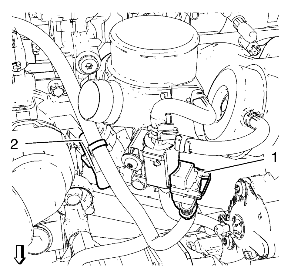
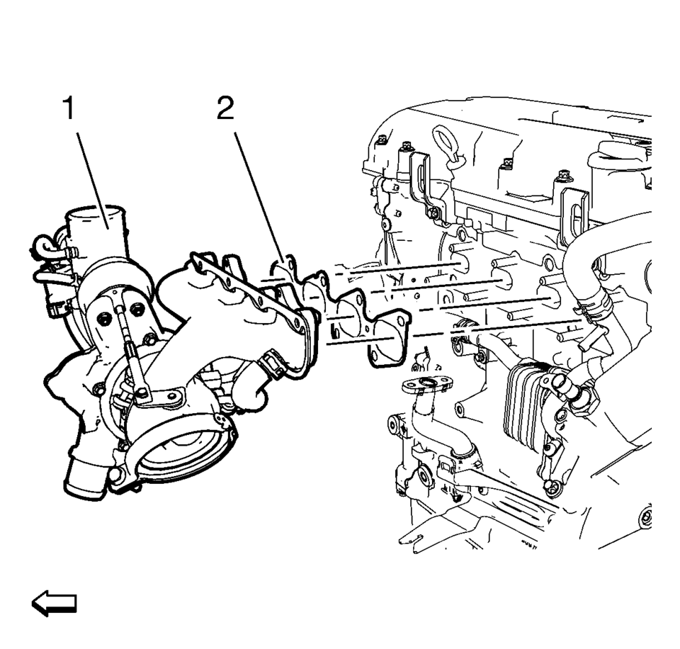
- Disconnect the turbocharger wastegate regulator solenoid valve wiring harness connector (1) and unclip wiring harness from retainer clip (2).
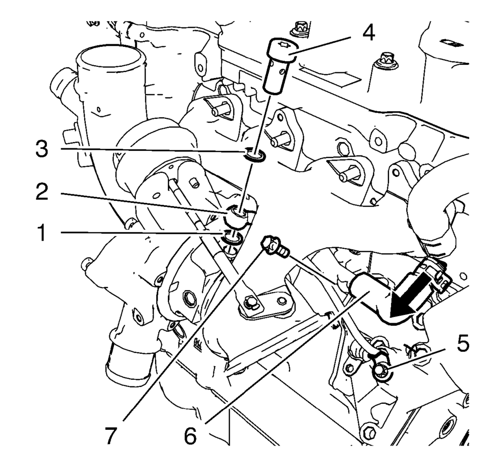
- Remove the turbocharger oil feed pipe hollow screw (4).
- Remove and DISCARD the 2 seal rings (1) and (3).
- Remove the turbocharger oil feed pipe bolt (5).
- Remove the turbocharger oil feed pipe (2).
- Loosen the turbocharger coolant return hose clamp and remove the turbocharger coolant return hose (6) from the oil cooler inlet pipe.
- Remove the turbocharger coolant return pipe bolt (7).
- Remove the charge air cooler inlet air hose from the turbocharger. Refer to Charge Air Cooler Inlet Air Hose Replacement.
- Remove the air conditioning bracket. Refer to Air Conditioning Compressor Bracket Removal.
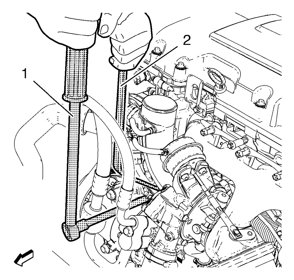
- Install the EN-49942 holding wrench (2) to the turbocharger coolant feed pipe. Guide a ratchet wrench (1) along with an extension through EN-49942 holding wrench to the turbocharger coolant feed pipe hollow screw.
- Loosen the turbocharger coolant feed pipe hollow screw with ratchet wrench and extension (1).
- Remove the turbocharger coolant feed pipe hollow screw.
- Remove and DISCARD the 2 seal rings.
- Remove the catalytic converter. Refer to Catalytic Converter Replacement.
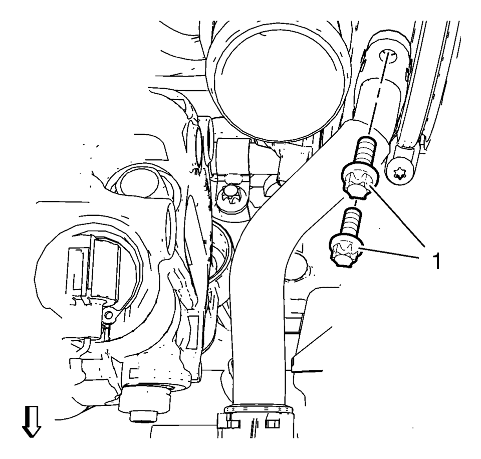
- Remove the 2 turbocharger oil return pipe bolts (1) from turbocharger.
- Remove the turbocharger oil return pipe from the turbocharger.
- Remove and DISCARD the gasket.
- Remove the wastegate actuator nuts and set aside.
- Remove and DISCARD the 8 turbocharger nuts (1).
- Remove the turbocharger assembly (1).
- Remove and DISCARD the turbocharger gasket (2).
- Remove the assembly parts from the turbocharger as necessary. Refer to Turbocharger Disassemble.
- If the turbocharger is being reused, refer to Turbocharger Cleaning and Inspection.
Note:
Close the screw bore in the turbocharger in order to avoid contamination.

Note:
EN-49942 holding wrench (2) should be installed to turbocharger coolant feed pipe as shown. The holding wrench should be installed to avoid twist of the turbocharger coolant feed pipe during the loosening procedure.
Note:
It is only necessary to move the wastegate actuator aside enough to access the manifold nuts.

- Installation Procedure
-
- Install the assembly parts to the turbocharger as necessary. Refer to Turbocharger Assemble.
- Clean the sealing surfaces.
- Install a NEW turbocharger gasket.
- Install the turbocharger assembly (1).
- Install the 8 NEW turbocharger nuts (1).
- Tighten the 8 turbocharger nuts in a sequence as shown to 8 Y (71 lb in)
.
- Repeat the tightening procedure to ensure a proper fastening of the turbocharger nuts.
- Install the wastegate actuator and nuts and tighten to 7 Y (62 lb in)
.
- Install a NEW gasket and the 2 turbocharger oil return pipe bolts (1)
and tighten to 8 Y (71 lb in)
.
- Install the catalytic converter. Refer to Catalytic Converter Replacement.
- Install the turbocharger coolant feed pipe to the engine block. Use the following procedure:

Caution:
Refer to Fastener Caution.
Caution:
Refer to Torque-to-Yield Fastener Caution.
Note:
It is only necessary to move the wastegate actuator aside enough to access the manifold nuts.
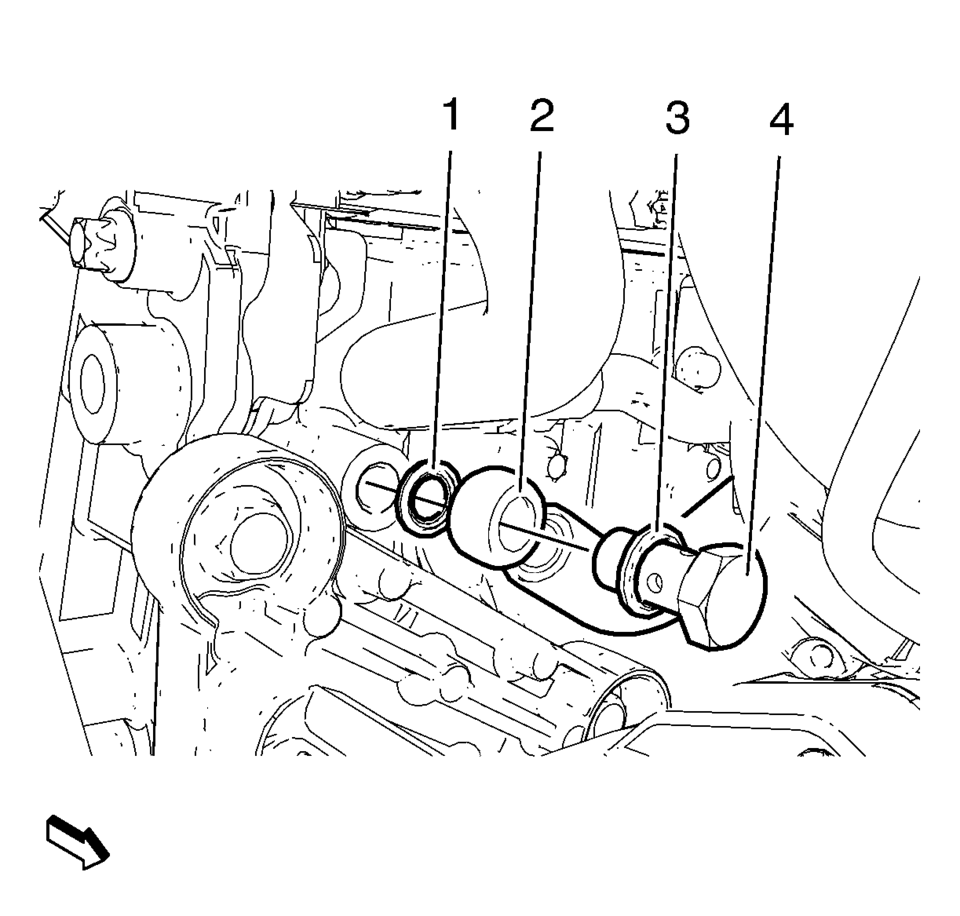
- Install a NEW seal ring (3) to the turbocharger coolant feed pipe hollow screw (4).
- Install the turbocharger coolant feed pipe hollow screw along with the seal ring to the turbocharger coolant feed pipe (2).
- Install a NEW seal ring (1) to the turbocharger coolant feed pipe hollow screw.
- Install the turbocharger coolant feed pipe hollow screw along with the turbocharger coolant feed pipe and the 2 seal rings to the engine.
Note:
The EN-49942 holding wrench should be installed in a perpendicular position as shown to ensure a proper installation position of the turbocharger coolant feed pipe.
- Install the EN-49942 holding wrench (2) to the turbocharger coolant feed pipe. Guide a ratchet wrench (1) along with an extension through EN-49942 holding wrench to the turbocharger coolant feed pipe hollow screw.
- Install the air conditioning bracket. Refer to Air Conditioning Compressor Bracket Installation.
Note:
EN-49942 holding wrench (2) should be installed to the turbocharger coolant feed pipe as shown. The holding wrench should be installed to avoid twist of the turbocharger coolant feed pipe during the fastening procedure.
- Tighten the turbocharger coolant feed pipe hollow screw with ratchet wrench and extension (1) to 30 Y (22 lb ft)
.
- Install the charge air cooler inlet air hose to the turbocharger. Refer to Charge Air Cooler Inlet Air Hose Replacement.
- Install the turbocharger coolant return pipe bolt (7) and tighten to 8 Y (71 lb in)
.
- Install the turbocharger coolant return hose (6) to the oil cooler inlet pipe.
- Install the turbocharger coolant return hose clamp.
- Install the turbocharger oil feed pipe (2) to the oil cooler and the turbocharger.
- Install the turbocharger oil feed pipe bolt (5).
- Install the turbocharger oil feed pipe hollow screw (4) along with the 2 NEW seal rings (1) and (3) and tighten to 30 Y (22 lb ft)
.
- Tighten the turbocharger oil feed pipe bolt to 10 Y (89 lb in)
.
- Connect the turbocharger wastegate regulator solenoid valve wiring harness connector (1) and clip in wiring harness to retainer clip (2).
- Install the exhaust manifold heat shield. Refer to Exhaust Manifold Heat Shield Replacement.
- Connect the positive crankcase ventilation pipe to the turbocharger.
- Install the air cleaner outlet duct. Refer to Air Cleaner Outlet Duct Replacement.
- Connect battery negative cable. Refer to Battery Negative Cable Disconnection and Connection.
- Fill the cooling system. Refer to Cooling System Draining and Filling.
- Use a scan tool to perform the Engine Control Module Setup for Component Replacement. Refer to Control Module References.
 Turbocharger Removal
Special Tool
EN-49942 Holding Wrench
For equivalent regional tools, refer to Special Tools.
Install the EN-49942 holding wrench (2) to the turbocharger coolant
feed pipe. Guid ...
 Turbocharger System Description
12
(1)
Turbocharger Bypass Solenoid Valve
(2)
Multifunction Intake Air Sensor
(3)
Turbocharger Wastegate Regulator Solenoid Valve
(4) ...
Other materials:
Overview (Radio with Touchscreen)
z VOL
y (Volume)
Press to decrease or increase the volume.
O (Power)
Press and hold to turn the power on or off.
D (Home Page)
Press to go to the Home Page. See Home Page.
...
Oil Pan Replacement
Special Tools
EN-49980 Guidance Pins
For equivalent regional tools, refer to Special Tools.
Removal Procedure
Remove the right front wheelhouse liner extension. Refer to Front Wheelhouse
Liner Inner Front Extension Replacement.
Remove the oil filter and drain the engine oi ...
Trip computer
Example
Basic information
In the Nissan Armada, the trip computer is controlled using intuitive switches
located directly on the steering wheel, allowing the driver to navigate menus without
distraction.
Scroll dial - in the Nissan Armada this control enables smooth navigation
throu ...

0.0052