Chevrolet Sonic Repair Manual: Body Hinge Pillar Lower Reinforcement Replacement
- Removal Procedure
-
- Disable the SIR system. Refer to SIR Disabling and Enabling.
- Disconnect the negative battery cable. Refer to Battery Negative Cable Disconnection and Connection.
- Remove all related panels and components.
- Repair as much of the damage as possible. Refer to Dimensions - Body.
- Remove the sealers and anti-corrosion materials from the repair area. Refer to Anti-Corrosion Treatment and Repair.
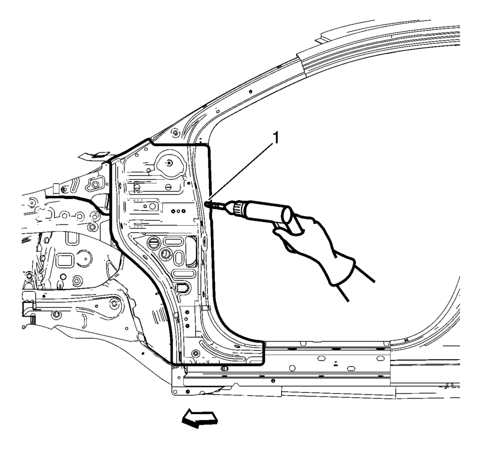
- Locate and mark all the necessary factory welds of the front hinge pillar body.
- Drill all factory welds (1). Note the number and location of welds for installation of the service assembly.
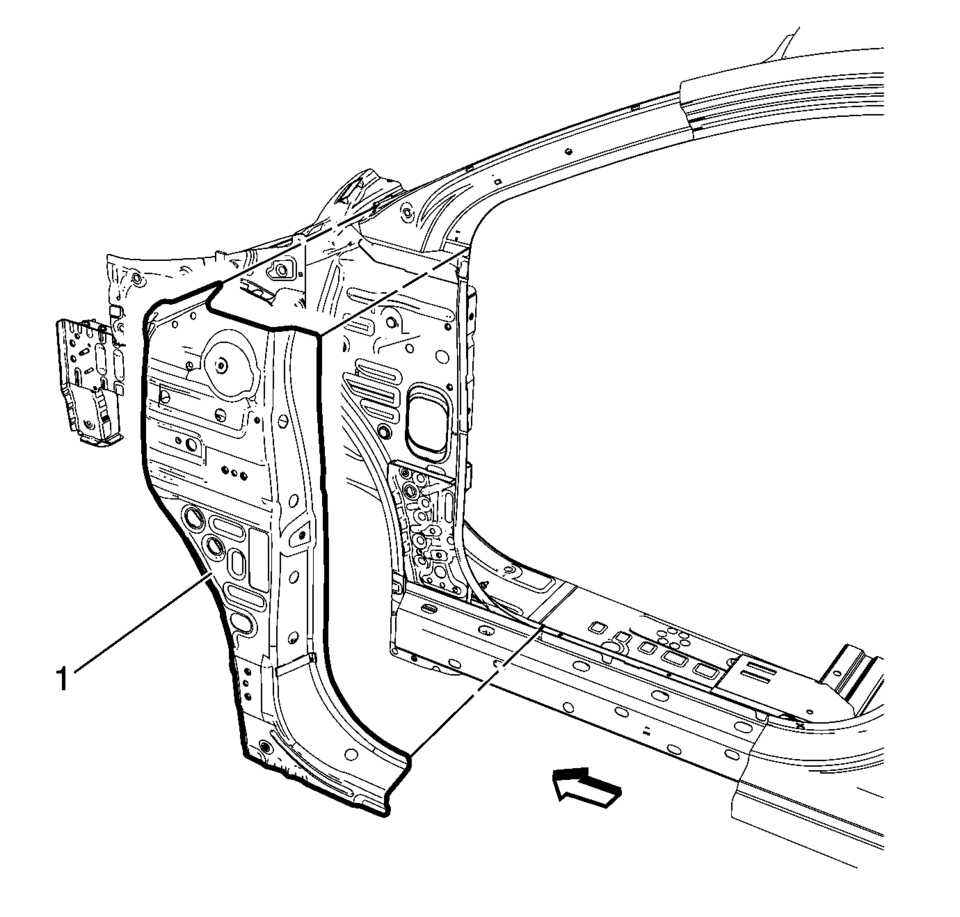
- Remove the damaged front hinge pillar body reinforcement (1).
Warning:
Refer to Approved Equipment for Collision Repair Warning.
- Installation Procedure
-
- Prepare all mating surfaces as necessary.
- Align the front hinge pillar body reinforcement.
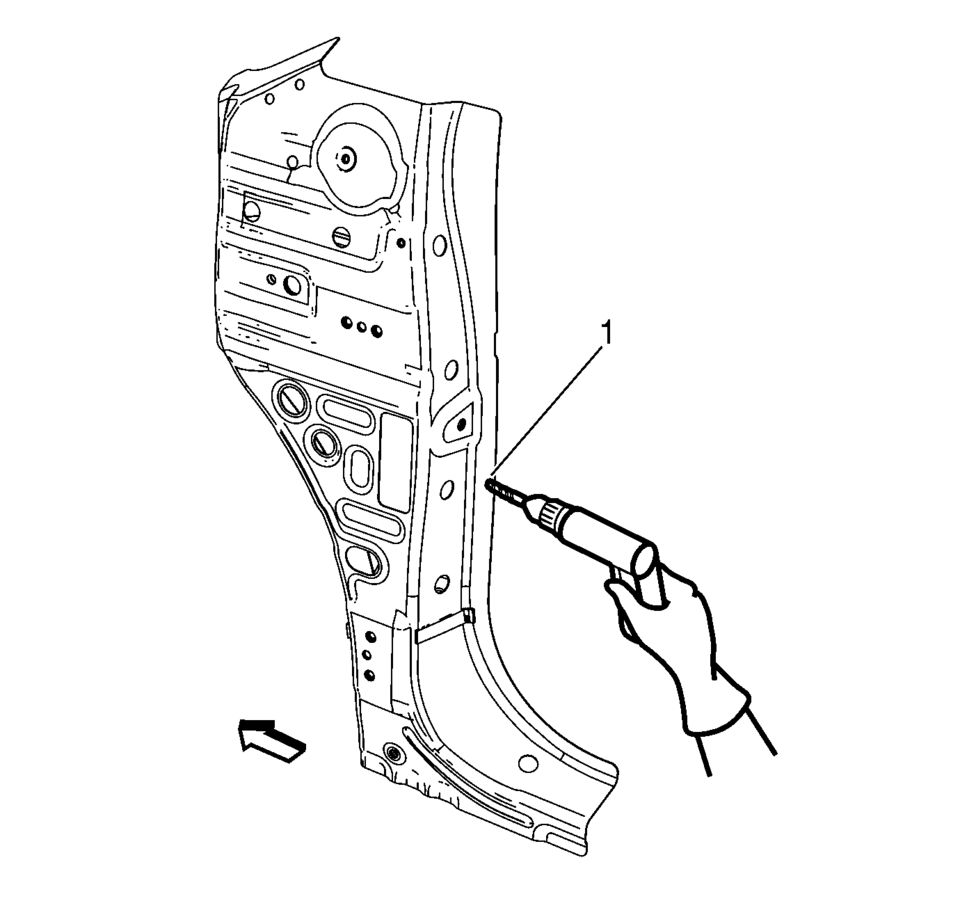
- Drill 8 mm (5/16 in)
holes for plug welding along the edges of the front hinge pillar body as noted from the original panel (1).
- Clean and prepare the attaching surfaces for welding.
- Position the front hinge pillar body reinforcement on the vehicle (1).
- Verify the fit of the front hinge pillar body reinforcement.
- Clamp the front hinge pillar body reinforcement into position.
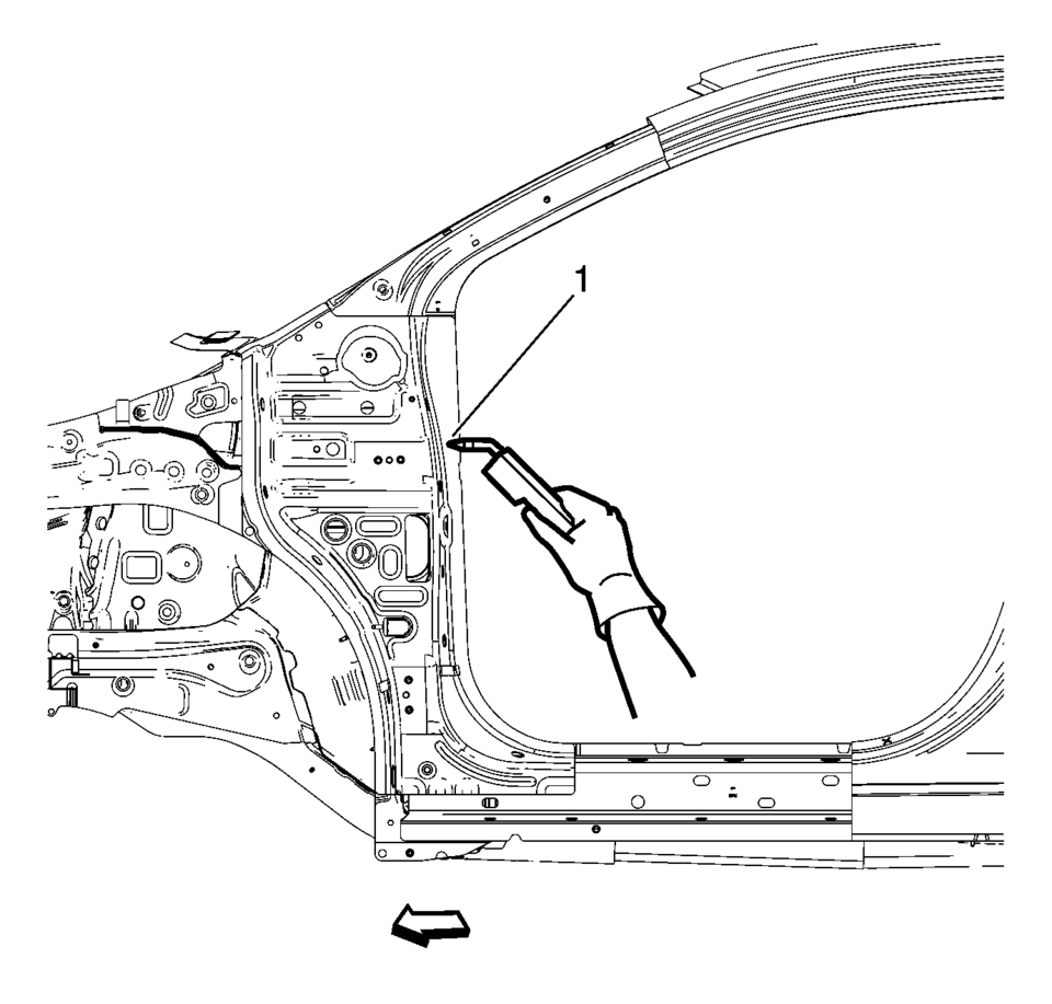
- Plug weld accordingly (1).
- Apply the sealers and anti-corrosion materials to the repair area, as necessary. Refer to Anti-Corrosion Treatment and Repair.
- Paint the repaired area. Refer to Basecoat/Clearcoat Paint Systems.
- Install all related panels and components.
- Connect the negative battery cable. Refer to Battery Negative Cable Disconnection and Connection.
- Enable the SIR system. Refer to SIR Disabling and Enabling.
 General
...
 Body Waterleak Repair
Warning: If the vehicle interior is exposed to moisture and becomes
soaked up to the level of the sensing and diagnostic module (SDM), the SDM and
SDM harness connector must be replaced. ...
Other materials:
Front Seats
The front seats have adjustable head restraints in the outboard seating positions.
Adjust the head restraint so that the top of the restraint is at the same height
as the top of the occupant's head. This position reduces the chances of a neck injury
in a crash.
The height of the head r ...
Radiator Outlet Hose Replacement (LDE LUW)
Special Tools
BO-38185 Hose Clamp Pliers
For equivalent regional tools, Refer to Special Tools.
Removal Procedure
Drain the cooling system. Refer to Cooling System Draining and Filling.
Remove the radiator outlet hose clamp (1) at the engine using BO-38185 ...
Crankshaft Balancer Removal
Special Tools
EN-652 Flywheel Holder
For equivalent regional tools, refer to Special Tools.
Install the EN-652 holder (1). Lock the flywheel (2) or the automatic
transmission flex plate via the starter ring gear.
Remove and DISCARD the crankshaft balancer bo ...

0.0095