Chevrolet Sonic Repair Manual: Brake Rotor Thickness Variation Measurement
Warning:
Refer to Brake Dust Warning.
Note:
Any disc brake rotor that exhibits thickness variation exceeding the maximum acceptable level must be refinished or replaced. Thickness variation exceeding the maximum acceptable level can cause brake pulsation.
- If the inboard friction surface of the brake rotor is not accessible, reposition and support the caliper with the brake pads. Refer to Front Disc Brake Pads Replacement.
- Clean the friction surfaces of the brake rotor with denatured alcohol, or an equivalent approved brake cleaner.
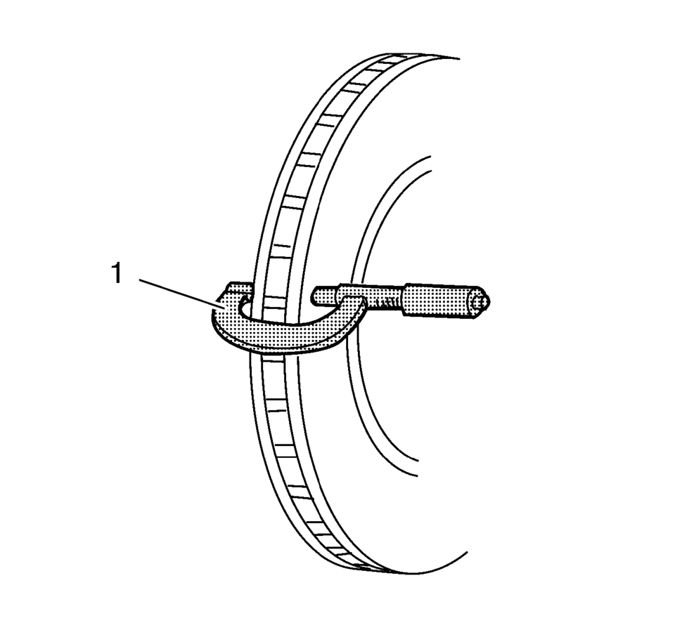
- Using a micrometer (1) calibrated in thousandths-of-a-millimeter, or ten-thousandths-of-an-inch,
measure and record the thickness of the brake rotor at 4 or more points, evenly
spaced around the brake rotor.
Make sure that the measurements are only taken within the friction surfaces and that the micrometer is positioned the same distance from the outer edge of the brake rotor, about 13 mm (1/2 in), for each measurement.
- Calculate the difference between the highest and lowest thickness measurements recorded to obtain the amount of thickness variation.
- Compare the thickness variation measurement to the following specification:
Specification
- J93, J94: 0.02 mm (0.0008 in)
- JPW, J97: 0.02 mm (0.0008 in)
- J93, J94: 0.02 mm (0.0008 in)
- If the brake rotor thickness variation measurement exceeds the specification, the brake rotor requires refinishing or replacement.
Note:
Whenever a brake rotor is refinished or replaced, the assembled lateral runout (LRO) of the brake rotor must be measured to make sure optimum performance of the disc brakes.
 Brake Rotor Thickness Measurement
Warning: Refer to Brake Dust Warning.
If the inboard friction surface of the brake rotor is not accessible, reposition
and support the caliper with the brake pads. Refer to Front Disc Bra ...
 Brake Rotor/Drum Balance Inspection
Support the vehicle drive axle on a suitable hoist. Refer to Lifting and
Jacking the Vehicle.
Remove the tire and wheel assemblies from the drive axle. Refer to Tire
and Wheel Removal and ...
Other materials:
Rear Compartment Floor Panel Carpet Replacement (Sedan)
Rear Compartment Floor Panel Carpet Replacement
Callout
Component Name
1
Rear Compartment Floor Panel Carpet Assembly
...
Supplemental Inflatable Restraint System Description and Operation
SIR System Overview
The supplemental inflatable restraint (SIR) system supplements the protection
offered by the seat belts. The SIR system contains an inflatable restraint sensing
and diagnostic module (SDM), air bags, seat belt pretensioners (anchor and retractor),
and impact sen ...
Air Cleaner Outlet Duct Replacement
Air Cleaner Outlet Duct Replacement
Callout
Component Name
1
Air Cleaner Outlet Duct Clamp
2
Air Cleaner Outlet Duct Clamp
3
Air Cleaner Outlet Duct
Tip: Ai ...

0.0071