
Chevrolet Sonic Repair Manual: Camber Description
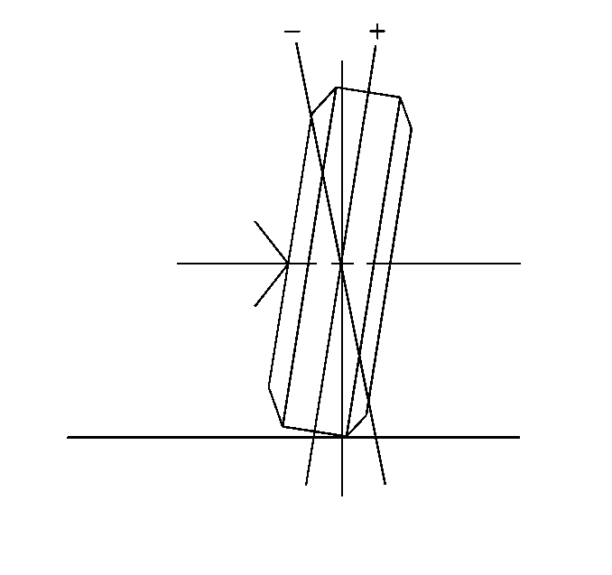
Camber is the tilting of the wheels from the vertical when viewed from the front of the vehicle. When the wheels tilt outward at the top, the camber is positive (+). When the wheel tilts inward at the top, the camber is negative (−). The amount of tilt is measured in degrees from the vertical. Camber settings influence the directional control and the tire wear.
Too much positive camber will result in premature wear on the outside of the tire and cause excessive wear on the suspension parts.
Too much negative camber will result in premature wear on the inside of the tire and cause excessive wear on the suspension parts.
Unequal side-to-side camber of 1 degree or more will cause the vehicle to pull or lead to the side with the most positive camber.
Cross Camber is the difference between the left camber value and the right camber value.
Cross Camber = L camber − R camber
 Aluminum Wheel Refinishing
Finish Damage Evaluation Procedure
Note:
If the wheels are chrome-plated, do not re-plate or refinish
the wheels.
If the wheels are polished aluminum, do not r ...
 Caster Description
Caster is the tilting of the uppermost point of the steering axis either forward
or backward, when viewed from the side of the vehicle. A backward tilt is positive (+)
and a forward tilt ...
Other materials:
Engine Compartment Fuse Block
LUV and LUW Engines
The engine compartment fuse block is on the driver side of the vehicle, near
the battery.
Caution
Spilling liquid on any electrical component on the vehicle may damage it.
Always keep the covers on any electrical component.
To access the fuses, press the clips together, ...
Windshield Wiper Blade Replacement
Windshield Wiper Blade Replacement
Callout
Component Name
Preliminary Procedure
Service Up and hold the wiper arm off the windshield when performing
the wiper blade replacement.
Pinch the two tabs on top of the wiper blad ...
Special Tools
Illustration
Tool Number/Description
EL 38758
EL 50074
J 38758
Parasitic Draw Test Switch
EL 50313
EL 42000
EL 50076
J 42000
...

0.0061