Chevrolet Sonic Repair Manual: Camshaft Position Actuator Adjuster Removal
Special Tools
- EN-6340 Camshaft Adjuster Locking Tool
- EN-6628-A Camshaft Locking Tool
For equivalent regional tools, refer to Special Tools.
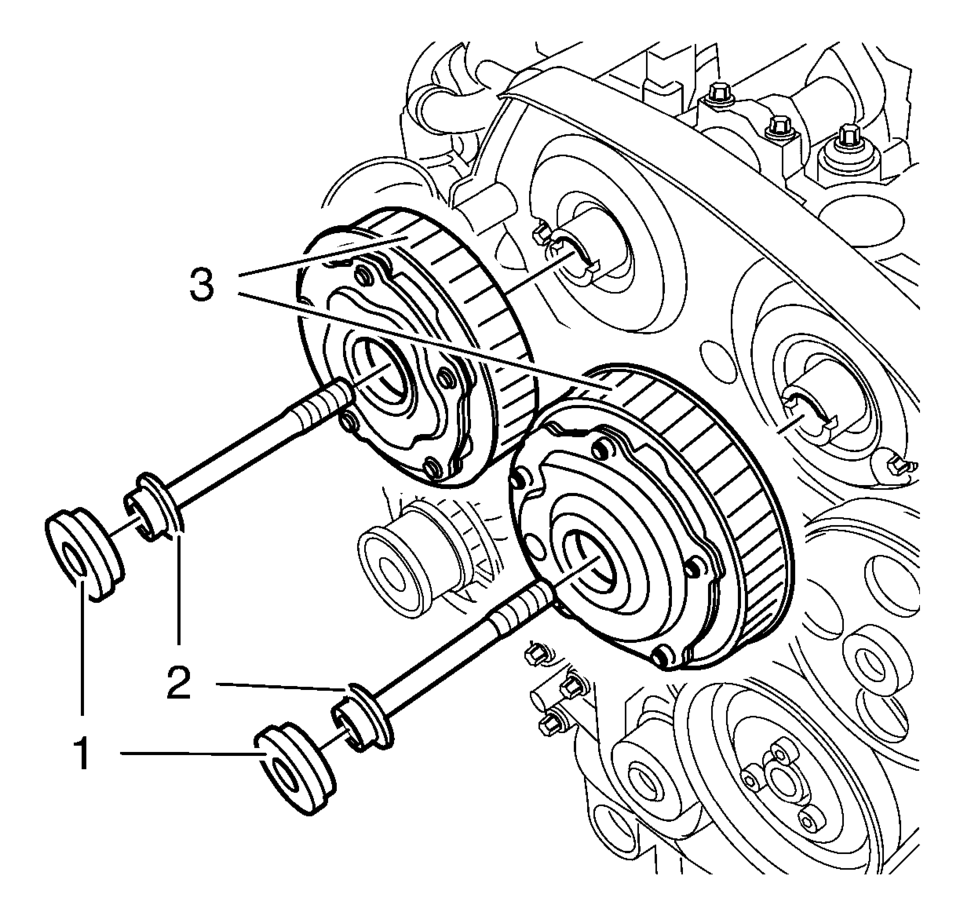
- Prepare the right half of the EN-6340 locking tool.
- Remove the 2 bolts (2).
- Remove the front panel (1) from the EN-6340 locking tool - right.
- Install the EN-6340 locking tool into the camshaft adjusters.

Note:
The right half of the EN-6340 locking tool can be recognized by the lettering "right", arrow, on the tool.
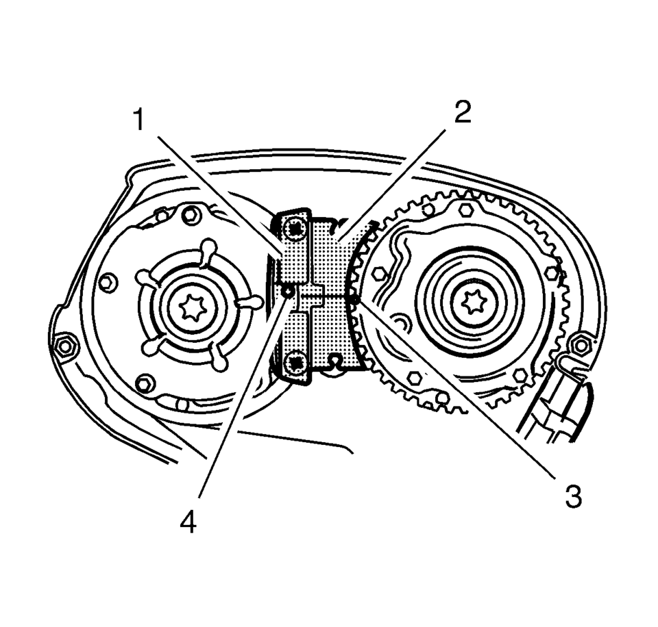
- Install the EN-6340 locking tool - left (1) into the camshaft adjusters as shown.
- Install EN-6340 locking tool - right (2) into the camshaft adjusters as shown.
Note:
The spot type marking (4) on the intake camshaft adjuster does not correspond to the groove of EN-6340 locking tool - left during this process but must be somewhat above as shown.
Note:
The spot type marking (3) on the exhaust camshaft adjuster must correspond to the groove on EN-6340 locking tool - right.
Note:
Note the arrows.

Note:
A second technician is required.
Note:
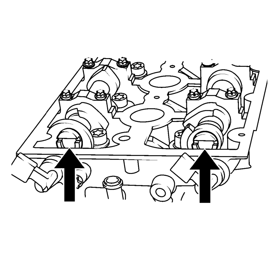
Use an appropriate open-end wrench in order to counterhold the camshaft hexagon. A thin cross-section wrench is required for a better fit. The usage of EN-6628-A locking tool is for the camshaft adjustment to prevent misalignment of the camshafts. The wrench is required to counterhold the camshafts during bolt torque procedure.
 Camshaft Position Actuator Adjuster Installation
Special Tools
EN-6340 Camshaft Adjuster Locking Tool
EN-6628-A Camshaft Locking Tool
EN-45059 Angle Meter
For equivalent regional tools, refer to Special Tools.
Note: Note t ...
 Camshaft Position Actuator Solenoid Valve Installation
Caution: The camshaft position actuator solenoid valves must be
kept parallel to the engine front cover during removal and installation.
The camshaft position actuator solenoid va ...
Other materials:
Malfunction Indicator Lamp
A computer system called OBD II (On-Board Diagnostics-Second Generation) monitors
the operation of the vehicle to ensure emissions are at acceptable levels, helping
to maintain a clean environment. The malfunction indicator lamp comes on when the
vehicle is placed in ON/RUN, as a check to show ...
Rear Brake Hose Replacement (Body to Axle - Disc Brake)
Removal Procedure
Warning: Refer to Brake Dust Warning.
Warning: Refer to Brake Fluid Irritant Warning.
Raise and support the vehicle. Refer to Lifting and Jacking the Vehicle.
Remove the tire and wheel assembly. Refer to Tire and Wheel Removal
and Install ...
Tire and Wheel Assembly-to-Hub/Axle Flange Match-Mounting
Note: After remounting a tire and wheel assembly to a hub/axle flange,
remeasure the tire and wheel assembly on-vehicle runout in order to verify that
the amount of runout has been reduced and brought to within tolerances.
Mark the location of the high spot on the tire and wheel asse ...

0.0077