Chevrolet Sonic Repair Manual: Control Solenoid Valve and Transmission Control Module Assembly Replacement
- Removal Procedure
-
- Remove the transmission control valve body cover. Refer to Control Valve Body Cover Replacement.
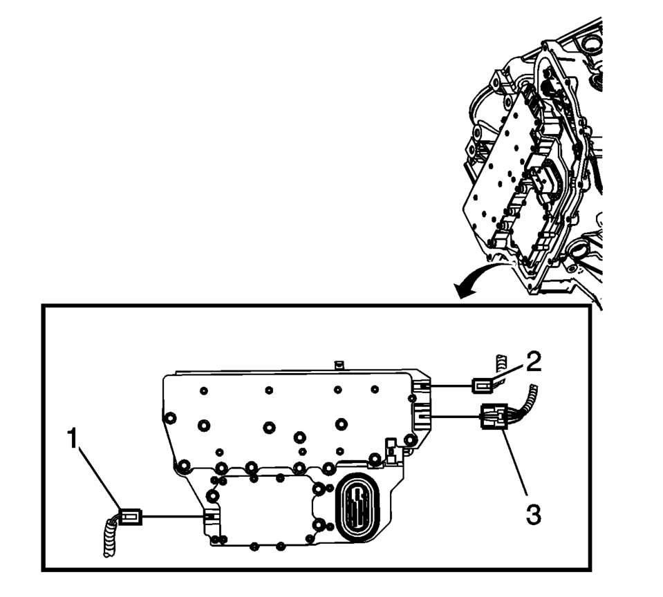
- Disconnect the output speed sensor electrical connector (2).
- Disconnect the shift position switch electrical connector (3).
- Disconnect the input speed sensor electrical connector (1).
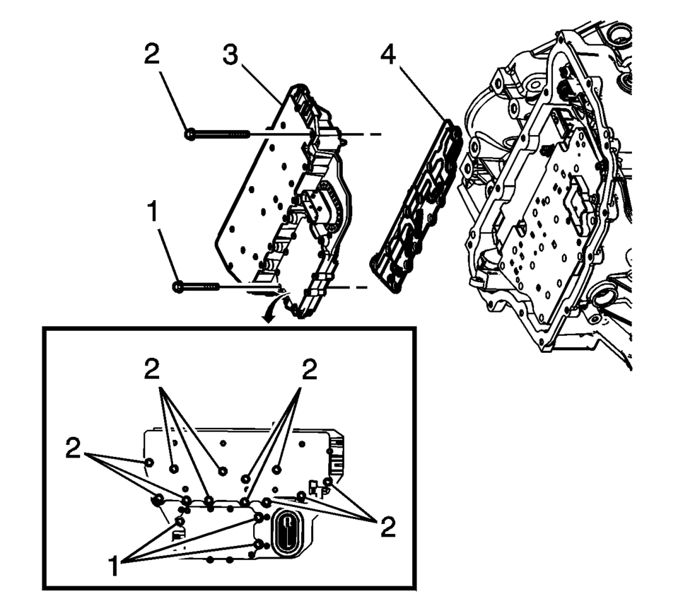
- Remove the 3 control solenoid valve assembly bolts (1) M5 x 40.5.
- Remove the 12 control solenoid valve assembly bolts (2) M6 x 97.
- Remove the control solenoid valve assembly with transmission control module (3).
- Remove the control solenoid valve assembly filter plate (4). Discard the filter plate. It is not reusable.
- Inspect the pressure switch seals for damage or contamination. Replace the control solenoid valve assembly as necessary.
- Inspect the channel plate bolt pass through holes for damage or burnelling. Any damage could cause leaking. Replace as necessary.
Caution:
Use care when removing or installing the filter plate assembly. A broken or missing retaining tab may not adequately secure the filter plate to the control solenoid valve assembly, resulting in possible damage or contamination.
- Installation Procedure
-
- Install a NEW control solenoid valve assembly filter plate (4) to prevent fluid leaks past the fluid seals.
- Install the control solenoid valve assembly with transmission control module (3).
- Hand start the control valve body bolts (1, 2).
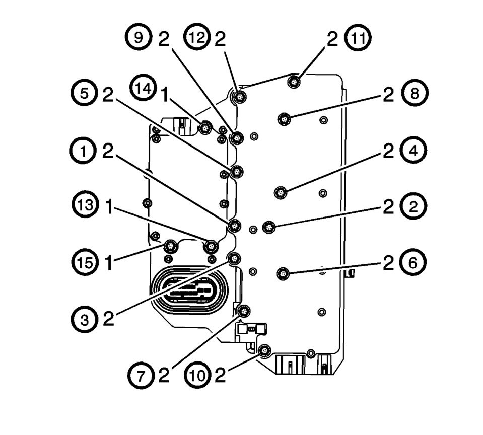
- Secure the 12 control solenoid valve assembly bolts (2) M6 x 97
and tighten in sequence to 12 Y (106 lb in)
.
- Secure the 3 control valve body bolts (1) M5 x 40.5
and tighten in sequence to 7 Y (62 lb in)
.
- Connect the input speed sensor electrical connector (1).
- Connect the output speed sensor electrical connector (2).
- Install the transmission control valve body cover. Refer to Control Valve Body Cover Replacement.
- After repairs, refer to Control Module References for programming and set up procedures.
- Perform the transmission adaptive values learn. Refer to Transmission Adaptive Values Learn.
Caution:
Use care when removing or installing the filter plate assembly. A broken or missing retaining tab may not adequately secure the filter plate to the control solenoid valve assembly, resulting in possible damage or contamination.
Caution:
Refer to Fastener Caution.
 Control Solenoid Valve and Transmission Control Module Assembly Installation
Control Solenoid Valve and Transmission Control Module Assembly Installation
Callout
Component Name
1
Control Solenoid V ...

Other materials:
Front Wheelhouse Liner Inner Front Extension Replacement (Left SIde)
Front Wheelhouse Liner Inner Front Extension Replacement
Callout
Component Name
Preliminary Procedure
Remove the tire and wheel assembly. Refer to Tire and Wheel Removal and
Installation.
1
Fron ...
Tread Wear Indicators Description
The original equipment tires have tread wear indicators that show when you should
replace the tires.
The location of these indicators are at 60 degree intervals around the outer
diameter of the tire. The indicators appear as a 6 mm (0.25 in) wide band when the
tire trea ...
Engine Flywheel Removal
Special Tools
EN-652 Flywheel Holder
For equivalent regional tools, refer to Special Tools.
Install EN-652 holder (1) to hold the engine flywheel (2).
Remove and DISCARD the 6 engine flywheel bolts (2).
Remove the engine flywheel (1). ...

0.0064