Chevrolet Sonic Repair Manual: Control Valve Body Cover Installation
|
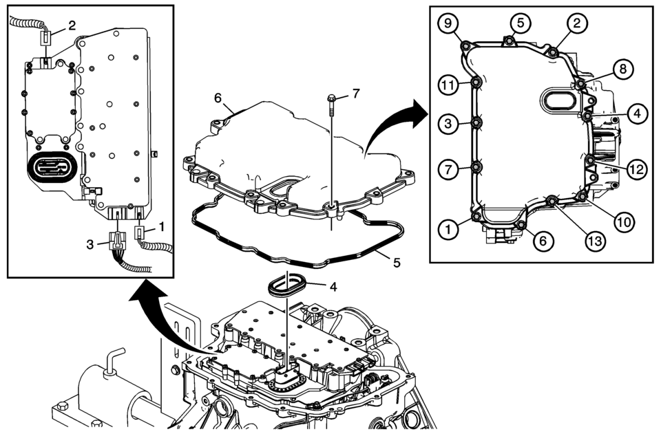
Callout |
Component Name |
|---|---|
|
1 |
Input Speed Sensor Connector |
|
2 |
Output Speed Sensor Connector |
|
3 |
Shift Position Switch Connector |
|
4 |
Control Valve Body Cover Wiring Connector Hole Seal Note: Do not re-use the valve body cover wiring connector hole seal. |
|
5 |
Control Valve Body Cover Gasket Note: Do not re-use the valve body cover gasket. |
|
6 |
Control Valve Body Cover |
|
7 |
Control Valve Body Cover Bolts M6 x 30 (Qty: 13) Caution: Refer to Fastener Caution.
12 Y (106 lb in) |
 Control Valve Body Cleaning and Inspection (Gen 2)
Control Valve Body Cleaning and Inspection
Callout
Component Name
Warning: Valve springs can be tightly compressed. Use care
...
 Control Valve Body Cover Replacement
Removal Procedure
Disconnect the battery negative cable. Refer to
Battery Negative Cable Disconnection and Connection.
Raise and support the vehicle. Refer to
Lifting and Jac ...
Other materials:
Brake System Warning Light
The vehicle brake system consists of two hydraulic circuits. If one circuit is
not working, the remaining circuit can still work to stop the vehicle. For normal
braking performance, both circuits need to be working
If the warning light comes on, there is a brake problem. Have the brake system ...
Front Compartment Fuse Block Replacement
Removal Procedure
Disconnect the battery negative cable. Refer to Battery Negative Cable
Disconnection and Connection.
Remove the junction block cover (1).
Remove the positive battery cable nut (1) from the junction block.
Remove the pos ...
The C300 competes well on fuel economy
Title: "2023 Mercedes-Benz C300: A Detailed Look at Efficiency, Interior, and Customization Options"
The 2023 Mercedes-Benz C300 presents a compelling choice for luxury sedan enthusiasts, offering a blend of performance, efficiency, and customizable features. Here's a breakdown of wh ...

0.0056