Chevrolet Sonic Repair Manual: Drive Belt Tensioner Replacement
Special Tools
- EN-955 Locking Pin
- EN-48488 Holding Wrench
For equivalent regional tools, refer to Special Tools.
- Removal Procedure
-
- Remove the right front wheelhouse liner extension. Refer to Front Wheelhouse Liner Inner Front Extension Replacement
- Install the engine support fixture. Refer to Engine Support Fixture.
- Remove the engine mount bracket. Refer to Engine Mount Bracket Replacement - Right Side.
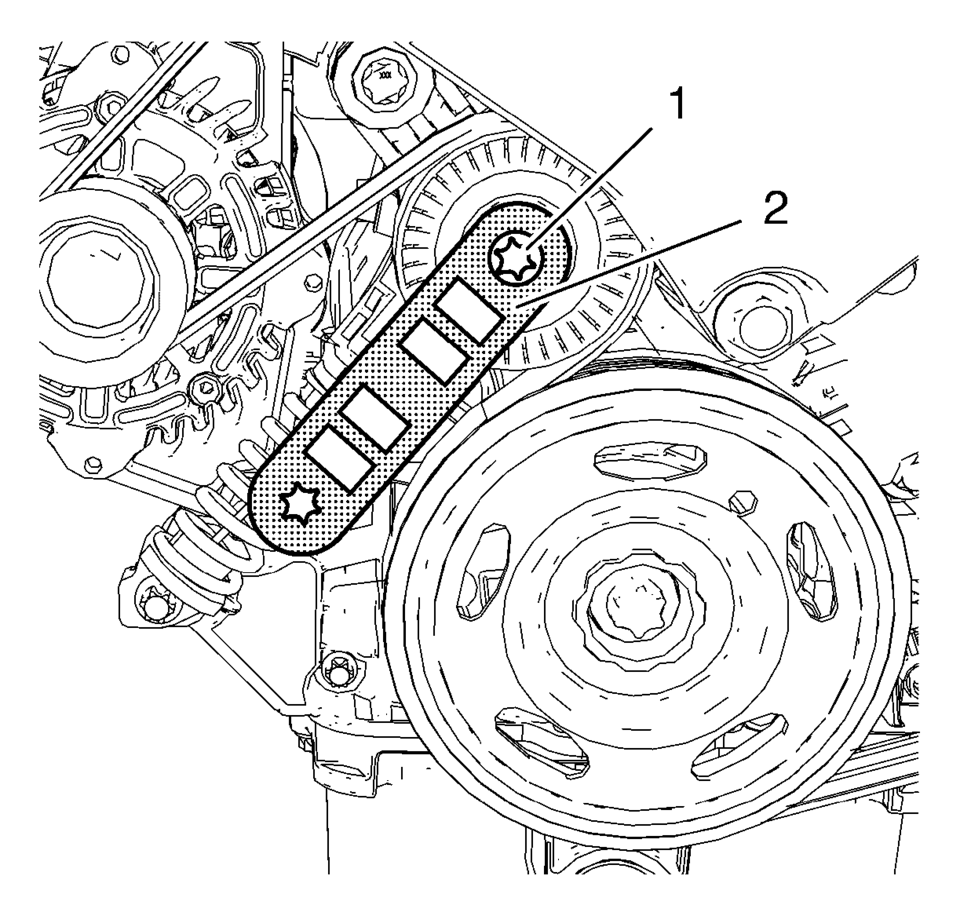
- Install the EN-48488 holding wrench (2) to the drive belt tensioner (1).
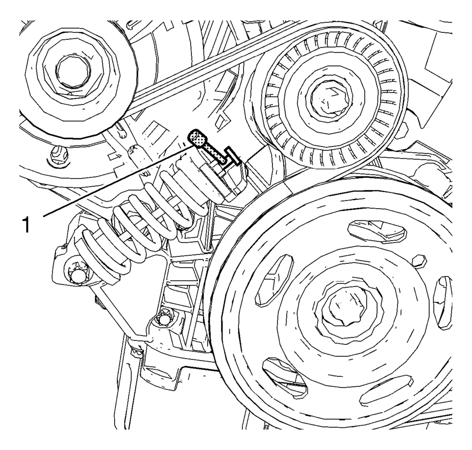
- Move the drive belt tensioner clockwise until the drive belt tensioner can be fixed with EN-955 locking pin (1).
- Remove the EN-48488 holding wrench .
- Remove the drive belt.
- Repeat steps 4 and 5 in order to remove the EN-955 locking pin from the drive belt tensioner.
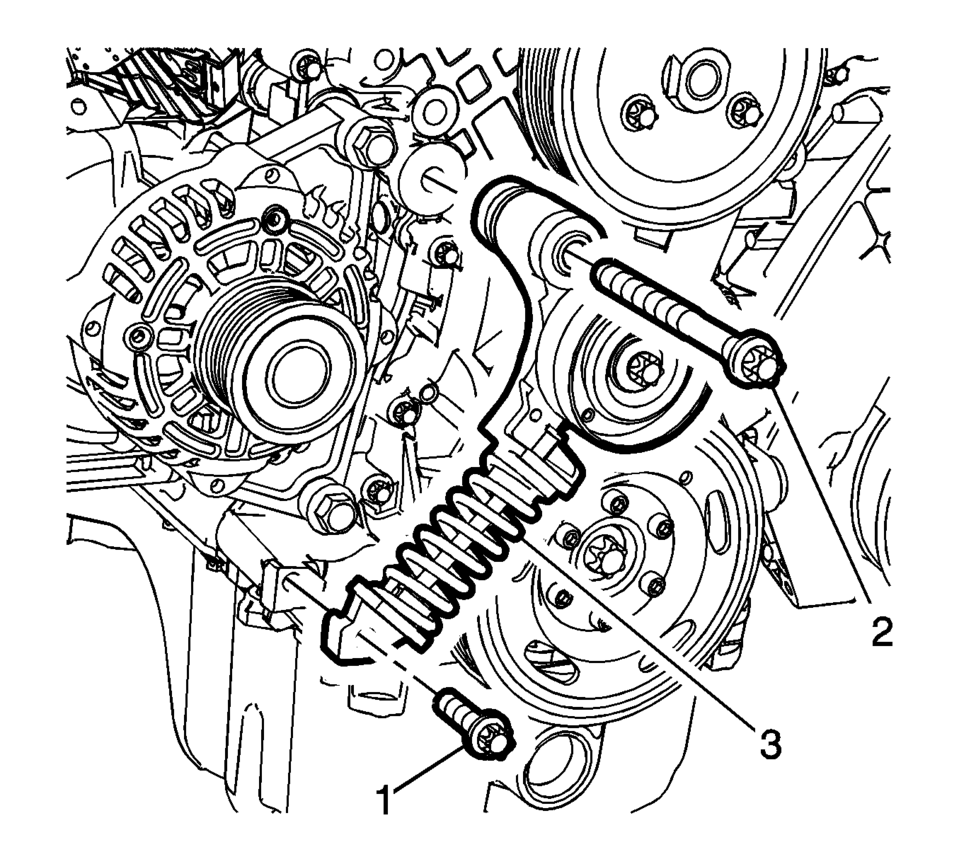
- Remove the lower drive belt tensioner bolt (1).
- Remove the upper drive belt tensioner bolt (2).
- Remove the drive belt tensioner (3).
- Installation Procedure
-
- Install the drive belt tensioner (3).
- Install the lower drive belt tensioner bolt (1).
- Install the upper drive belt tensioner bolt (2).
- Tighten the lower drive belt tensioner bolt (1) to 22 Y (16 lb ft)
.
- Tighten the upper drive belt tensioner bolt (2) to 55 Y (41 lb ft)
.
- Install the EN-48488 holding wrench (2) to drive belt tensioner (1).
- Move the drive belt tensioner clockwise until the drive belt tensioner can be fixed with EN-955 locking pin (1).
- Install the drive belt.
- Move the drive belt tensioner clockwise until EN-955 locking pin can be removed.
- Allow the tensioner to slide back slowly.
- Remove the EN-48488 holding wrench .
- Install the engine mount bracket. Refer to Engine Mount Bracket Replacement - Right Side.
- Install the right front wheelhouse liner extension. Refer to Front Wheelhouse Liner Inner Front Extension Replacement.
- Remove the engine support fixture. Refer to Engine Support Fixture.
Caution:
Refer to Fastener Caution.
Note:
Engine mount bracket is removed.
 Drive Belt Tensioner Removal
Remove the drive belt tensioner bolt (1).
Remove the drive belt tensioner (2).
...
 Drive Belt Installation
Special Tools
EN-955 Locking Pins
EN-48488 Holding Wrench
For equivalent regional tools, refer to Special Tools.
Note: Ensure that the drive belt tensioner is held with EN-955?E
...
Other materials:
Wheel Alignment and Tire Balance
The tires and wheels were aligned and balanced at the factory to provide the
longest tire life and best overall performance. Adjustments to wheel alignment and
tire balancing are not necessary on a regular basis. Consider an alignment check
if there is unusual tire wear or the vehicle is signi ...
Tire Pressure Monitor Operation
This vehicle may have a Tire Pressure Monitor System (TPMS). The TPMS is designed
to warn the driver when a low tire pressure condition exists. TPMS sensors are mounted
onto each tire and wheel assembly, excluding the spare tire and wheel assembly.
The TPMS sensors monitor the air pressure in ...
Throttle Body Heater Inlet Pipe Replacement (LUW)
Throttle Body Heater Inlet Pipe Replacement
Callout
Component Name
Preliminary Procedure
Drain the cooling system. Refer to Cooling System Draining and Filling.
1
Throttle Body Heater Inlet Pipe
...

0.0067