Chevrolet Sonic Repair Manual: Drivetrain and Front Suspension Frame Replacement
Special Tools
EN-45059 Angle Meter
For equivalent regional tools, refer to Special Tools.
- Removal Procedure
-
- Support the radiator and condenser from above using the upper brackets on each side.
- Raise the vehicle on a hoist. Refer to Lifting and Jacking the Vehicle.
- Remove the front tire and wheel assembly. Refer to Tire and Wheel Removal and Installation.
- Remove the skid plate from the front frame, if equipped. Refer to Drivetrain and Front Suspension Frame Skid Plate Replacement.
- Remove the left and right front wheel house liner inner front extensions. Refer to Front Wheelhouse Liner Inner Front Extension Replacement.
- Remove the front bumper impact bar lower bracket. Refer to Front Bumper Impact Bar Lower Bracket Replacement.
- Disconnect the steering linkage tie rod end from the steering knuckle. Refer to Steering Linkage Outer Tie Rod Replacement.
- Disconnect the lower ball joints from the steering knuckles. Refer to Lower Control Arm Replacement.
- Disconnect the stabilizer links from the strut assemblies.
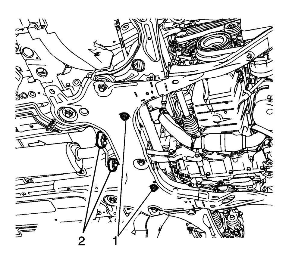
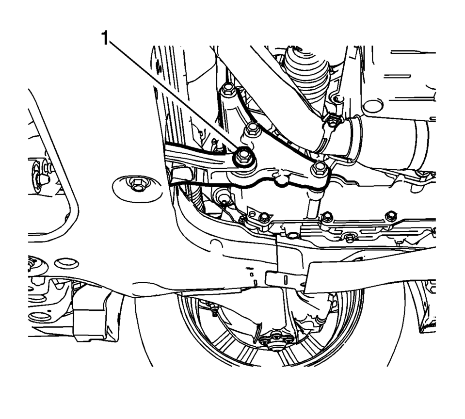
- Remove the steering rack retaining bolts?€‰(1) and discard.
- Using mechanics wire, secure the power steering gear to the vehicle.
- Disconnect the hydraulic power steering hoses from the front frame, if equipped.
- Disconnect the exhaust isolators?€‰(2) from the front suspension frame.
- Disconnect the power brake booster pump hose and connector, if equipped.
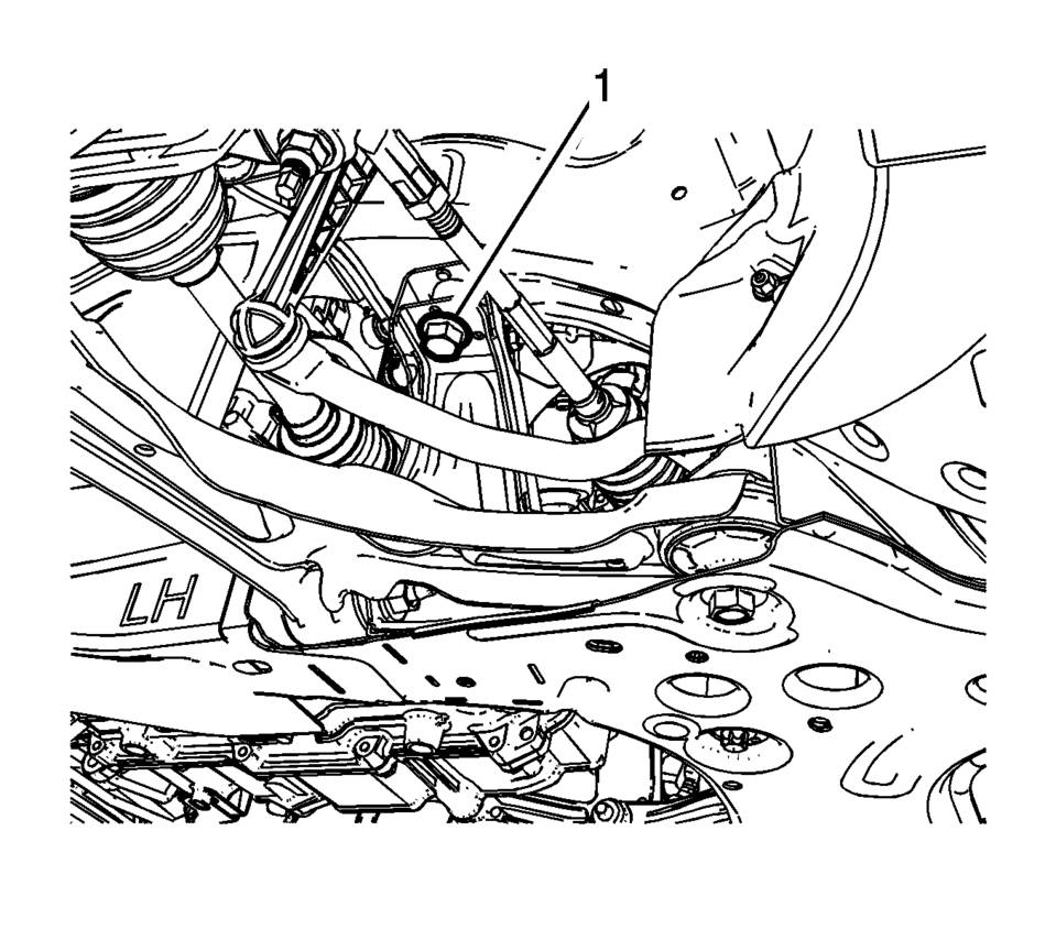
- Remove the rear transmission mount bracket to rear mount through bolt?€‰(1).
- Remove both frame support braces.
- Using a suitable support table or equivalent, support the front suspension frame.
- Remove the upper frame suspension retaining bolts?€‰(1).
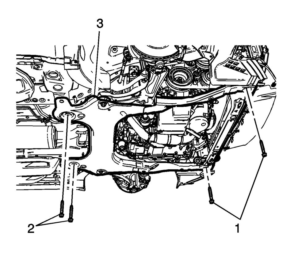
- Remove the frame?€‰front bolts?€‰(1).
- Remove the frame?€‰rear bolts?€‰(2).
- Remove the frame?€‰(3) from the vehicle.
- Remove the following components, if replacing the frame:
- The lower control arms?€”Refer to Lower Control Arm Replacement.
- The stabilizer shaft?€”Refer to Stabilizer Shaft Replacement.
- The front bumper lower impact bar?€”Refer to Front Bumper Lower Impact Bar Replacement.
- The power brake booster pump, if equipped?€”Refer to Power Brake Booster Pump Replacement.
- Installation Procedure
-
- Install the following components on the drivetrain and front suspension frame if removed:
- The power brake booster pump, if equipped?€”Refer to Power Brake Booster Pump Replacement.
- The front bumper lower impact bar?€”Refer to Front Bumper Lower Impact Bar Replacement.
- The stabilizer shaft?€”Refer to Stabilizer Shaft Replacement.
- The lower control arms?€”Refer to Lower Control Arm Replacement.
- Install the frame?€‰(3) into the vehicle.
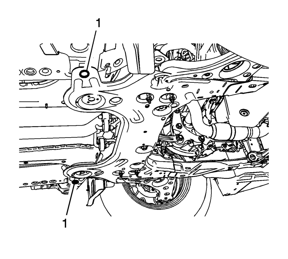
- Using two suitable drifts for adjusting pins, have an assistant vertically insert and hold the drifts through the front suspension frame and floor panel?€‰(1).
Caution:
Refer to Fastener Caution.
- Install the frame rear bolts?€‰(2) and tighten to 135?€‰Y (100?€‰lb?€‰ft)
.
- Install the frame front bolts?€‰(1) and tighten to 58?€‰Y (43?€‰lb?€‰ft)
.
- Install the upper frame suspension retaining bolts?€‰(1) and tighten to 135?€‰Y (100?€‰lb?€‰ft)
- Install the frame braces and tighten the fasteners to 22?€‰Y (16?€‰lb?€‰ft)
.
- Remove the support for the power steering gear.
- Install the steering gear retaining fasteners?€‰(1). Refer to Steering Gear Replacement.
- Connect the hydraulic power steering hoses to the front frame, if equipped.
- Connect the exhaust isolators?€‰(2) to the front suspension frame.
- Install the rear transmission mount bracket to rear mount through bolt?€‰(1). Refer to Transmission Rear Mount Replacement.
- Connect the power brake booster pump hose and connector, if equipped.
- Connect the lower ball joints to the steering knuckles. Refer to Lower Control Arm Replacement.
- Connect the stabilizer links to the strut assemblies. Refer to Stabilizer Shaft Link Replacement.
- Connect the steering linkage tie rod end to the steering knuckle. Refer to Steering Linkage Outer Tie Rod Replacement.
- Install the front bumper impact bar lower bracket. Refer to Front Bumper Impact Bar Lower Bracket Replacement.
- Install the left and right front wheel house liner inner front extensions. Refer to Front Wheelhouse Liner Inner Front Extension Replacement.
- Install the skid plate to the front frame, if equipped. Refer to Drivetrain and Front Suspension Frame Skid Plate Replacement.
- Install the front tire and wheel assembly. Refer to Tire and Wheel Removal and Installation.
- Lower the vehicle.
- Remove the support of the radiator and condenser.
 Body Side Upper Front Applique Replacement
Body Side Upper Front Applique Replacement
Callout
Component Name
Caution: Refer to Exterior Trim Emblem Removal Caution.
...
 Drivetrain and Front Suspension Frame Skid Plate Replacement
Removal Procedure
Raise and support the vehicle. Refer to Lifting and Jacking the Vehicle.
Remove the mounting bolts?€‰(1) for the front suspension frame skid
p ...
Other materials:
Liftgate Hinge Replacement
Liftgate Hinge Replacement
Callout
Component Name
Preliminary Procedures
Remove the liftgate. Refer to Liftgate Replacement.
Lower the rear of the headliner to access the inner bolts. Refer
to Headlining Trim Panel Replac ...
Rear Axle Replacement
Removal Procedure
Raise and support the vehicle. Refer to Lifting and Jacking the Vehicle.
Remove the tires and wheel assembly. Refer to Tire and Wheel Removal
and Installation.
Remove the park brake cables from the rear axle. Refer to Parking Brake
Cable Replacement. ...
Differential Case Disassemble
Special Tools
6-9607346 Sensor Ring Gear Puller
J-810704 Steering Column Center Bar Puller
J-810721 Axle Shaft Seal Remover Support Base
R-0006749 Support Base
R-0407011 Bearing Race Remover
R-0007761 Universal Handle for Pullers and Installers
S-9407195 Pinion Gear Case Bearing ...

0.0063