Chevrolet Sonic Repair Manual: Engine Oil Cooler Inlet Pipe Replacement (LUW)
- Removal Procedure
-
- Drain the cooling system. Refer to Cooling System Draining and Filling.
- Remove the exhaust manifold with catalytic converter. Refer to Exhaust Manifold with Catalytic Converter Replacement.
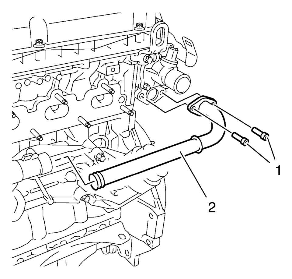
- Remove the engine oil cooler pipe bolts (1) and the engine oil cooler pipe (2).
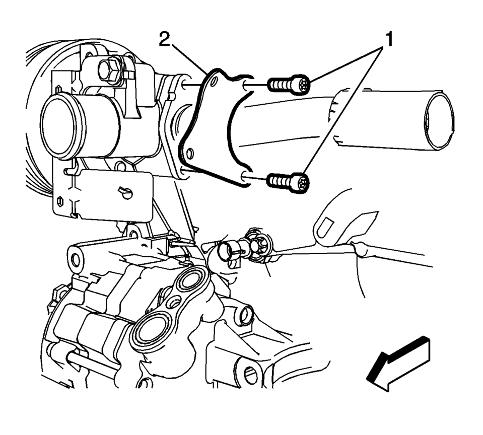
- Remove the engine oil cooler outlet pipe bolts (1) and the engine oil cooler outlet pipe bracket (2).
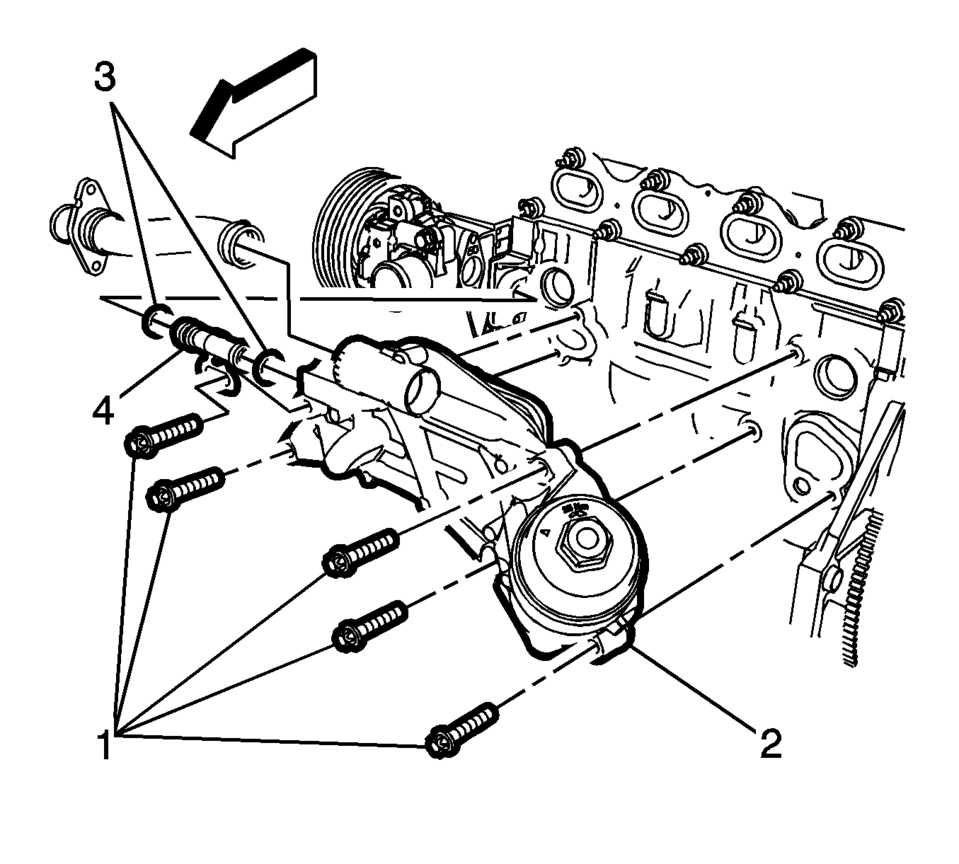
- Remove the engine oil cooler assembly bolts (1) and remove the cooler (2).
- Remove the engine oil cooler inlet pipe (4) and seals (3).
- Installation Procedure
-
- Replace the seals on the engine oil cooler outlet pipe and the engine oil cooler pipe.
- Install the engine oil cooler inlet pipe (4) with NEW seals (3) to the engine oil cooler assembly.
- Position the engine oil cooler assembly (2) to the engine block.
- Install the engine oil cooler assembly bolts (1) and tighten to 25 Y
(19 lb ft)
.
- Install the engine oil cooler outlet pipe mounting bolts (1) and the
bracket (2) to the water pump housing and tighten to 8 Y (71 lb in)
.
- Install the engine oil cooler pipe (3) to the thermostat housing and
tighten bolts (1) to 8 Y (71 lb in)
.
- Install the exhaust manifold with catalytic converter. Refer to Exhaust Manifold with Catalytic Converter Replacement.
- Fill the cooling system. Refer to Cooling System Draining and Filling.
- Start the engine and check for coolant leaks.
Caution:
Refer to Fastener Caution.
 Engine Oil Cooler Coolant Inlet Hose Replacement (LUV)
Engine Oil Cooler Coolant Inlet Hose Replacement
Callout
Component Name
Preliminary Procedure
Open the hood.
Drain the cooling ...
 Engine Oil Cooler Outlet Hose Replacement (LUV)
Engine Oil Cooler Outlet Hose Replacement
Callout
Component Name
Preliminary Procedure
Drain the cooling system. Refer to Cooling S ...
Other materials:
Inflatable Restraint Sensing and Diagnostic Module Programming and Setup
Special Tools
EL-49642 SPS Programming Support Tool
For equivalent regional tools, refer to Special Tools.
Note:
DO NOT program a control module unless directed to by a service procedure
or a service bulletin. If the ECU is not properly configured with the correct
calibration ...
SIR Service Precautions
General Service Instructions
Warning: When performing service on or near the SIR components
or the SIR wiring, the SIR system must be disabled. Refer to SIR Disabling
and Enabling . Failure to observe the correct procedure could cause deployment
of the SIR components, person ...
Tread Wear Indicators Description
The original equipment tires have tread wear indicators that show when you should
replace the tires.
The location of these indicators are at 60 degree intervals around the outer
diameter of the tire. The indicators appear as a 6 mm (0.25 in) wide band when the
tire trea ...

0.0086