Chevrolet Sonic Repair Manual: Heater Outlet Hose Replacement (LDE, LUW)
Special Tools
BO-38185 Hose Clamp Pliers
For equivalent regional tools, refer to Special Tools.
- Removal Procedure
-
- Drain the cooling system. Refer to Cooling System Draining and Filling.
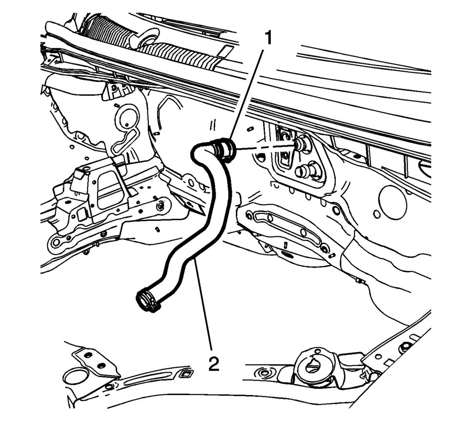
- Disengage the heater outlet hose quick connect clip (1) at the heater core.
- Remove the heater outlet hose (2) from the heater core.
- Remove the heater outlet hose clamp (1) at the engine using BO-38185 Hose Clamp Pliers .
- Remove the heater outlet hose (2) from the engine.
- Remove the heater outlet hose from the vehicle.

- Installation Procedure
-
- Install the heater outlet hose to the vehicle.
- Install the heater outlet hose (2) to the engine.
- Install the heater outlet hose clamp (1) at the engine using BO-38185 Hose Clamp Pliers .
- Install the heater outlet hose (2) to the heater core.
- Engage the heater outlet hose quick connect clip (1) at the heater core.
- Fill the cooling system. Refer to Cooling System Draining and Filling.
Note:
The quick connector has an internal anti-rotation feature. The ensure the quick connector is properly aligned to the heater core pipe, position the white mark to the 12:00 O’clock position during installation.
 Heater Inlet Hose Replacement (LUV)
Heater Inlet Hose Replacement
Callout
Component Name
Preliminary Procedures
Drain the engine coolant. Refer to Cooling System Drain ...
 Heater Outlet Hose Replacement (LUV)
Heater Outlet Hose Replacement
Callout
Component Name
Preliminary Procedures
Drain the engine coolant. Refer to Cooling System Drai ...
Other materials:
Front Floor Console Cover Replacement (Manual Transmission)
Removal Procedure
Use a flat bladed plastic trim tool in order to release the retainers
securing the console cover?€‰(1) to the console assembly.
Reach under the console cover assembly?€‰(1) and release the retainer
tabs securing the transmission shif ...
Brake Warning System Description and Operation
Brake Warning Indicator
Brake Warning Block Diagram
B80Park
Brake
SwitchB20Brake
Fluid Level
SwitchK9Body
Control
ModuleP16Instrument
Cluster
Hard-Wired
Serial D ...
Master Cylinder Reservoir Filling
Warning: Refer to Brake Fluid Irritant Warning.
Caution: Refer to Brake Fluid Effects on Paint and Electrical Components
Caution.
Visually inspect the brake fluid level through the brake master cylinder
reservoir.
If the brake fluid level is at or below the half-full point ...

0.0074