Chevrolet Sonic Repair Manual: Lock Cylinder Coding - Ignition
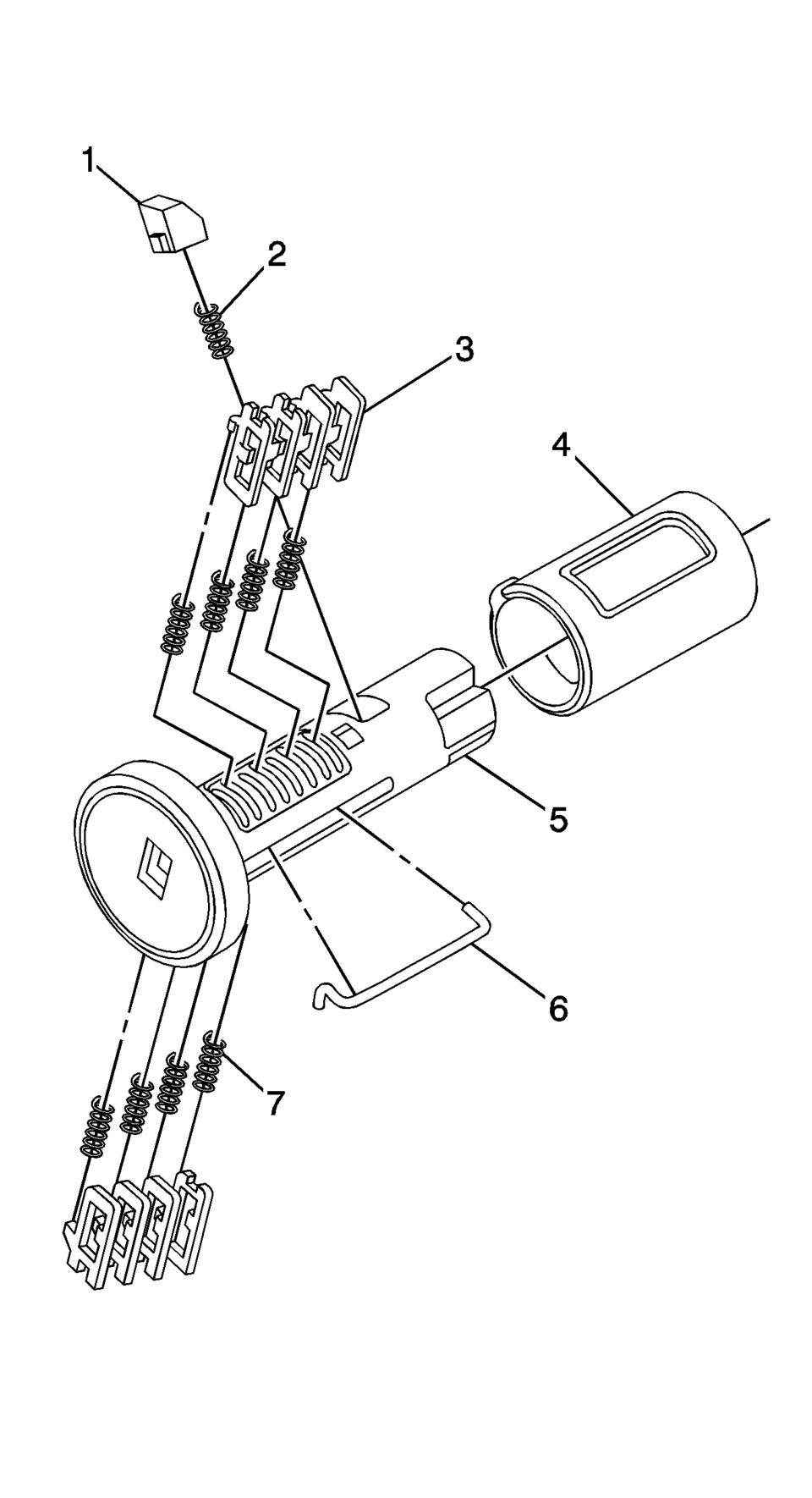
The ignition lock cylinder uses 8 key cut positions, 1–8. The ignition cylinder tumblers (3) are located on alternate sides of the cylinder (5). They are not snap-in and are not self-retaining. It follows the key code with the first tumbler being the first depth of the key code, closest to the head of the key.
- Hold the ignition cylinder assembly (5) so the side with the tumbler spring pocket located closest to the head of the cylinder is facing up.
- Insert the tumbler spring (7) into each of the 4 spring pockets of the cylinder assembly. This side of the cylinder used left tumblers.
- The first tumbler (3) to be loaded will be the first key cut position, which is the first number in the key code. Install the tumbler in the slot over the spring. Install the remaining right tumblers following the key code and same process, pressing the tumblers in place until they are secure.
- Rotate the cylinder assembly. Insert the tumbler spring into each of the spring pockets of the cylinder assembly. This side of the cylinder used right tumblers.
- The first tumbler (3) to be loaded will be the second key cut position, the second number in the key code. Install the first tumbler in the slot over the spring. Install the remaining left tumblers following the key code and same process, pressing the tumblers in place until they are secure.
- Inspect for correct loading of the tumblers by inserting the key into the cylinder. All tumblers should drop flush with the lock cylinder body diameter.
- With the key in the cylinder assembly insert the round connector (6), insert the retainer spring (2) in the retainer slot located in the cylinder assembly. Insert the retainer (1) lining it up in the slot over the spring. Depress the retainer and hold.
- Insert the cylinder into the sleeve (4) as shown in the print. Make sure the actuator stays located properly in the cylinder.
- When the key is removed, the lock should stay together.
- Lightly lubricate the outside surface in the tumbler area of in the lock body and down the key slot using the provided grease. Insert and extract the key 5 times to lubricate the keyway.
- Insert the key and function the lock 3 times to distribute the grease inside the sleeve.
- Verify the key position for inserting the lock into the column.
Note:
All lock cylinders for side milled keys have right and left tumblers. The location of the tooth of the tumbler determines whether it is right of left. Illustrations in this procedure show the right tumblers on the top and the left tumblers on the bottom. All tumblers are marked 1R, 1L, 2R, or 2L. The number being cut depth and the letter meaning right or left.
 Front Side Door Lock Cylinder Rod Replacement
Front Side Door Lock Cylinder Rod Replacement
Callout
Component Name
Preliminary Procedure
Remove the rear side door window rear gu ...
 Rear Compartment Lid Lock Cylinder Coding
The rear compartment lid lock cylinder uses 7 of the 7 cut positions. The tumbler
positions are staggered from side to side, 4 on one side and 3 on the other, are
not self-retaining, and ...
Other materials:
Rear Side Door Weatherstrip Replacement - Body Side
Rear Side Door Weatherstrip Replacement - Body Side
Callout
Component Name
Preliminary Procedures
Remove the upper center pillar trim. Refer to Center Pillar Upper
Trim Panel Replacement.
Remove the lower center pillar tr ...
Wheel Replacement
Replace any wheel that is bent, cracked, or badly rusted or corroded. If wheel
nuts keep coming loose, the wheel, wheel bolts, and wheel nuts should be replaced.
If the wheel leaks air, replace it. Some aluminum wheels can be repaired. See your
dealer if any of these conditions exist.
Your d ...
Hub/Axle Flange and Wheel Stud Runout Inspection
Special Tools
GE-8001 Dial Indicator Set , or equivalent
Raise and support the vehicle. Refer to Lifting and Jacking the Vehicle.
Mark the location of the wheels to the wheel studs and mark the specific
vehicle position on each tire and wheel ?ELF, LR, RF, RR.
Remove the tire and w ...

0.0084