Chevrolet Sonic Repair Manual: Steering Column Replacement
- Removal Procedure
-
- The steering column
- The intermediate shaft(s)
- The steering gear
- With the steering wheel in the straight ahead position, LOCK the steering column.
- Remove the upper trim cover and the lower trim cover from the steering column. Refer to Steering Column Lower Trim Cover Replacement.
- Remove the instrument panel lower trim pad cover. Refer to Instrument Panel Lower Trim Pad Cover Replacement.
- Remove the left side floor air outlet duct. Refer to Floor Air Outlet Duct Replacement - Left Side.
- Disconnect any electrical connectors as necessary.
- Use paint in order to place match marks on the intermediate steering shaft (1) and on the steering gear pinion shaft (3).
- Remove the intermediate steering shaft lower bolt (2).
- Disconnect the intermediate steering shaft from the steering gear pinion shaft.
- Support the steering column.
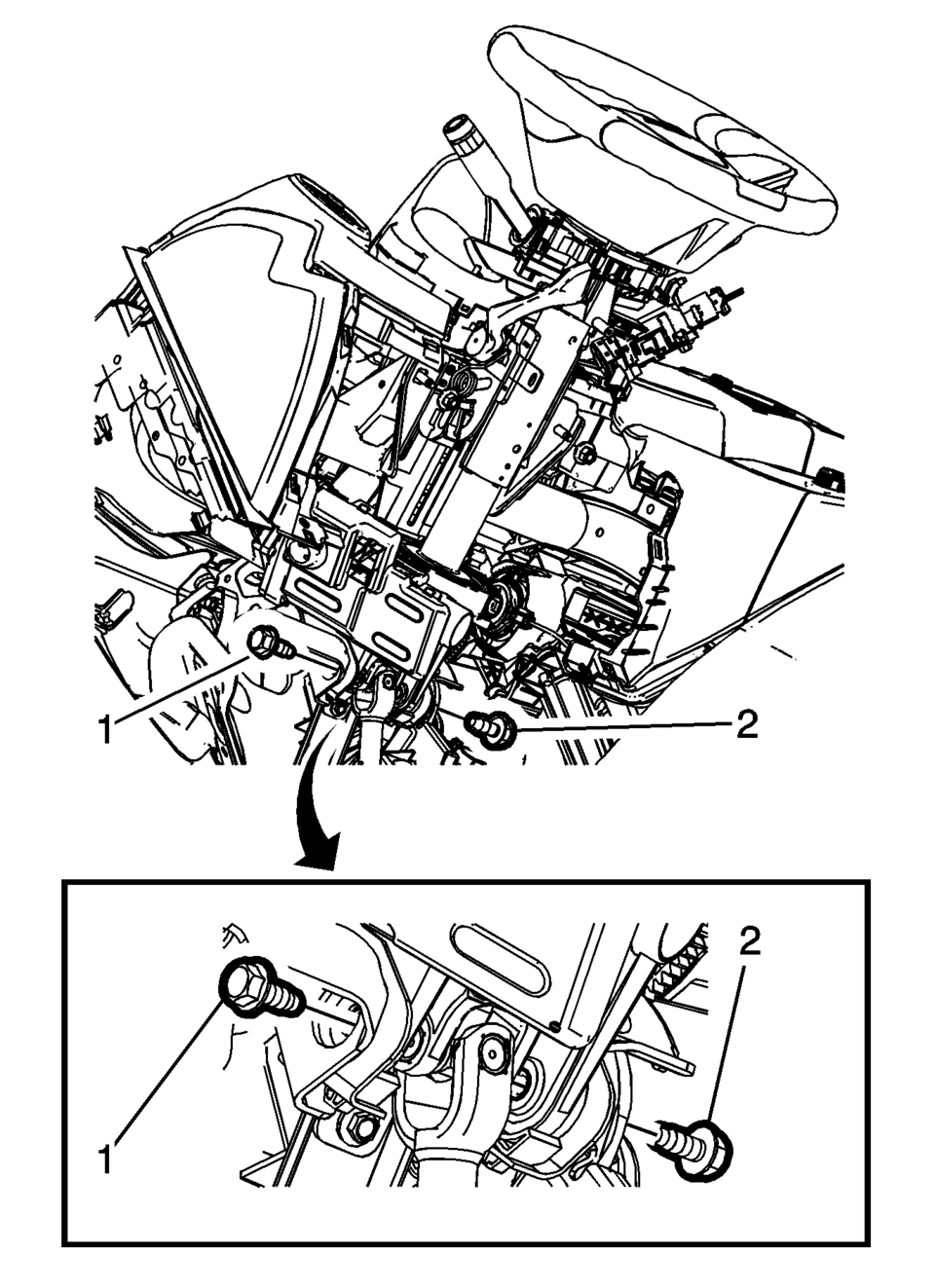
- Remove the 2 steering column lower support bracket bolts (1, 2).
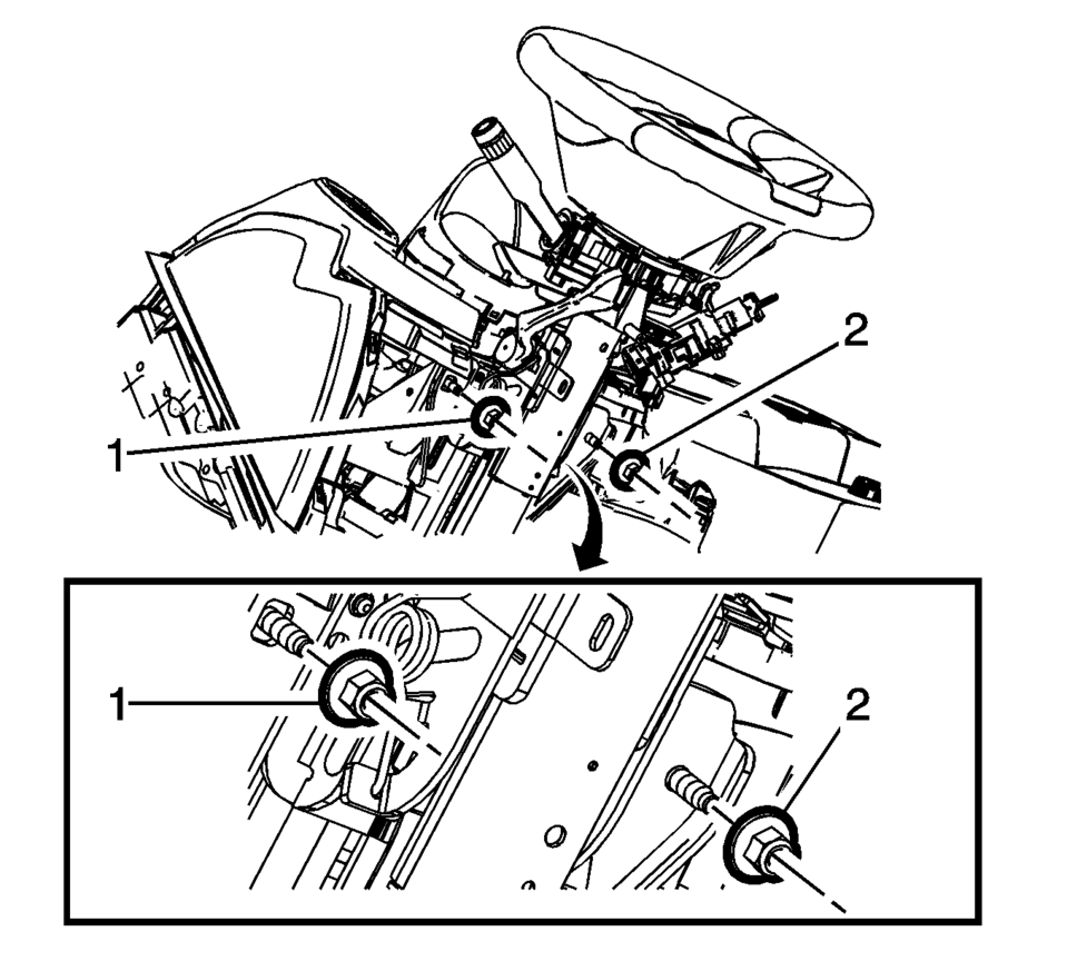
- Remove the 2 steering column upper support bracket nuts (1, 2).
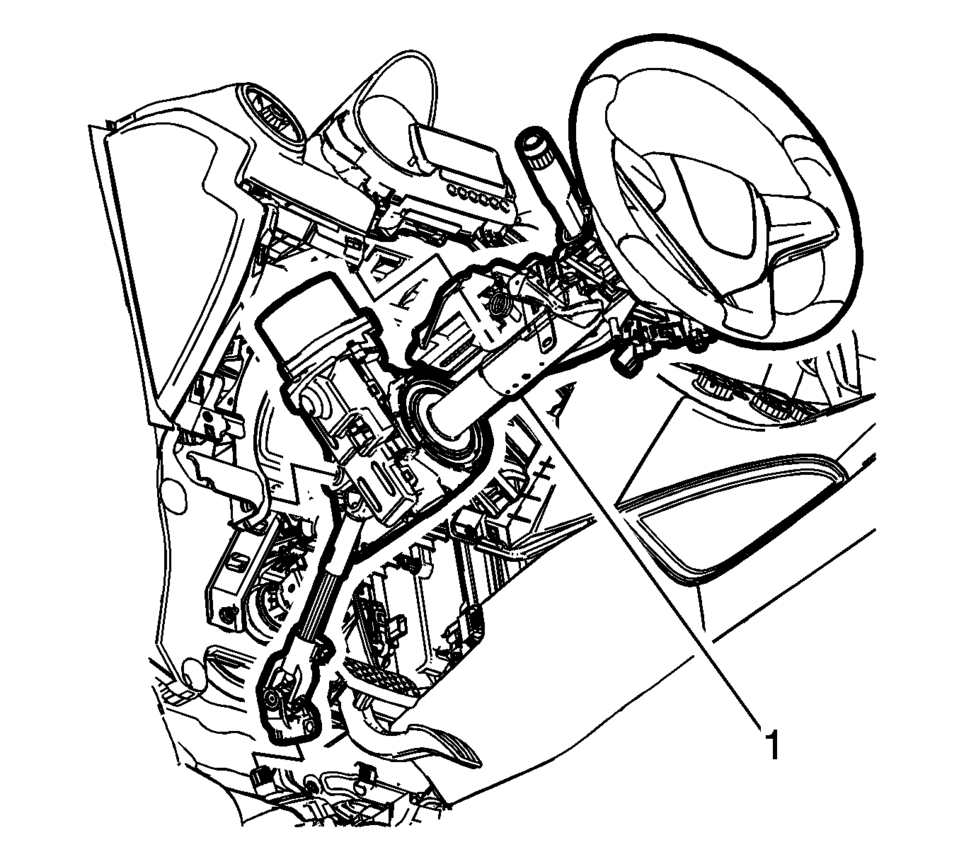
- Remove the steering column assembly (1) from the vehicle.
- Transfer components as necessary.
Caution:
With wheels of the vehicle facing straight ahead, secure the steering wheel utilizing steering column anti-rotation pin, steering column lock, or a strap to prevent rotation. Locking of the steering column will prevent damage and a possible malfunction of the SIR system. The steering wheel must be secured in position before disconnecting the following components:
After disconnecting these components, do not rotate the steering wheel or move the front tires and wheels. Failure to follow this procedure may cause the SIR coil assembly to become un-centered and cause possible damage to the SIR coil. If you think the SIR coil has become un-centered, refer to your specific SIR coil’s centering procedure to re-center SIR Coil.

Caution:
Do not support the steering column by only the lower or upper support bracket. Damage to the column lower bearing adapter could result.
Caution:
Once the steering column is removed from the vehicle, the column is extremely susceptible to damage. Dropping the column assembly on the end could collapse the steering shaft or loosen the plastic injections, which maintain column rigidity. Leaning on the column assembly could cause the jacket to bend or deform. Any of the above damage could impair the columns collapsible design. Do NOT hammer on the end of the shaft, because hammering could loosen the plastic injections, which maintain column rigidity. If you need to remove the steering wheel, refer to the Steering Wheel Replacement procedure in this section.
- Installation Procedure
-
- If you are replacing the steering column or the intermediate steering shaft, copy the match marks from the old parts to the new parts.
- Position the steering column assembly (1) in the vehicle.
- Align the match marks and connect the intermediate steering shaft to the steering gear pinion shaft.
- Tighten the steering column lower fasteners before you tighten the steering column upper fasteners. Failure to do this can damage the steering column.
- Tighten the steering column fasteners to the specified torque. Overtightening the upper steering column fasteners could affect the steering column collapse.
- Install, but do not tighten, the 2 steering column upper support bracket nuts (1, 2).
- Install, but do not tighten, the 2 steering column lower support bracket bolts (1, 2).
- Install the intermediate steering shaft lower bolt (2) and tighten to
49 Y (36 lb ft)
.
- Tighten the 2 steering column lower support bracket bolts to 22 Y
(16 lb ft)
.
- Tighten the 2 steering column upper support bracket nuts to 22 Y
(16 lb ft)
.
- Connect any electrical connectors as necessary.
- Install the left side floor air outlet duct. Refer to Floor Air Outlet Duct Replacement - Left Side.
- Install the instrument panel lower trim pad cover. Refer to Instrument Panel Lower Trim Pad Cover Replacement.
- Install the upper trim cover and the lower trim cover to the steering column. Refer to Steering Column Lower Trim Cover Replacement.
- Setup the power steering control module. Refer to Power Steering Control Module Programming and Setup.
- Center the steering angle sensor. Refer to Steering Angle Sensor Centering.
Caution:
Do NOT allow the wiring harness to be pinched between the motor/module assembly and the steering column during installation. A pinched harness will cause diagnostic trouble codes to be set and may require replacement of the steering column.
Warning:
In order to ensure the intended function of the steering column in a vehicle during a crash and in order to avoid personal injury to the driver, perform the following:
Caution:
Ensure all fasteners are securely seated before applying needed torque. Failure to do so may result in component damage or malfunctioning of steering column.
Caution:
Refer to Fastener Caution.
 Steering Column Lower Trim Cover Replacement
Steering Column Lower Trim Cover Replacement
Callout
Component Name
Preliminary Procedure
Remove the instrument panel steering ...
 Steering Column Upper Trim Cover Replacement
Steering Column Upper Trim Cover Replacement
Callout
Component Name
1
Instrument Panel Steering Column Upper Trim Cover ...
Other materials:
Overview (Radio with CD/USB)
91011121314151617
O /VOL (Power/Volume)
Turns the system on or off and adjusts the volume.
Z (Eject)
Removes a disc from the CD slot.
Buttons 1−6
Radio: Saves and selects favorite stations.
AUX Port
3.5 mm (1/8 in) connection for external devices.
...
Tread Wear Indicators Description
The original equipment tires have tread wear indicators that show when you should
replace the tires.
The location of these indicators are at 60 degree intervals around the outer
diameter of the tire. The indicators appear as a 6 mm (0.25 in) wide band when the
tire trea ...
Front Wheelhouse Liner Inner Front Extension Replacement (Right Side, LUV)
Front Wheelhouse Liner Inner Front Extension Replacement
Callout
Component Name
Preliminary Procedure
Remove the tire and wheel assembly. Refer to Tire and Wheel Removal
and Installation.
Remove the front fascia opening l ...

0.0047