Chevrolet Sonic Repair Manual: Steering Gear Boot Replacement
Special Tools
CH-804 Tensioner
For equivalent regional tools, refer to Special Tools.
- Removal Procedure
-
- Raise and support the vehicle. Refer to Lifting and Jacking the Vehicle.
- Remove the steering linkage outer tie rod. Refer to Steering Linkage Outer Tie Rod Replacement.
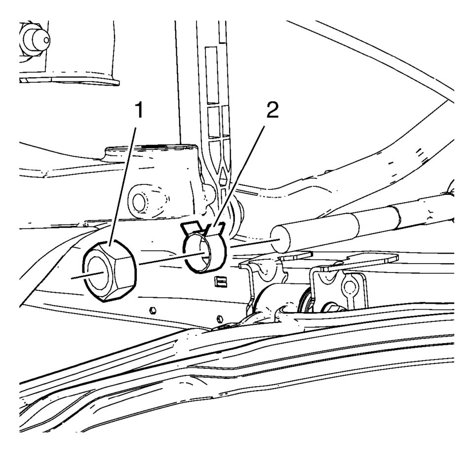
- Remove the steering linkage inner tie rod nut (1).
- Remove the steering gear boot outer clamp (2).
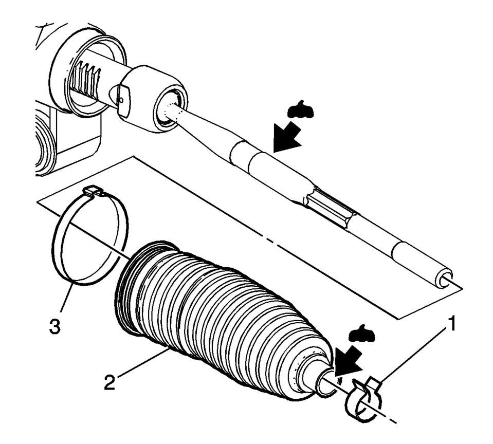
- Remove the steering gear boot inner clamp (3). Discard the clamp.
- Remove the steering gear boot (2).
- Clean the steering linkage inner tie rod and the steering gear boot contact area of any lubricant or debris.
Note:
Place match marks on the steering linkage inner tie rod nut and the steering linkage inner tie rod before removing. During installation of the nut, align the match marks.
- Installation Procedure
-
- Install a new steering gear boot inner clamp (3) loosely on the steering gear boot (2).
- Apply the lubricant from the service kit to the steering linkage inner tie rod and to the steering gear boot (2).
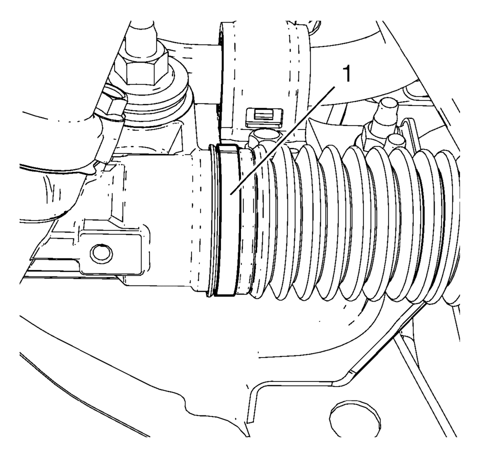
- Install the steering gear boot (2) over the steering linkage inner tie rod and onto the steering gear.
- Use the CH-804 tensioner in order to crimp the inner steering gear boot clamp (1).
- Install the steering gear outer boot clamp (2).
- Install the steering linkage inner tie rod nut (1).
- Install the steering linkage outer tie rod. Refer to Steering Linkage Outer Tie Rod Replacement.
- After installation is complete, measure and adjust the front toe. Refer to Wheel Alignment - Steering Wheel Angle and/or Front Toe Adjustment.
Note:
The steering gear boot must seat in the appropriate groove on the steering gear.
 Special Tools
Illustration
Tool Number/ Description
CH-161-B
DT-161-B
KM-161-B
J-22888-20A
Bearing Puller
...
 Steering Gear Replacement
Steering Gear Replacement
Callout
Component Name
Caution: With wheels of the vehicle facing straight ahead,
secure the st ...
Other materials:
Steering Linkage Outer Tie Rod Replacement
Steering Linkage Outer Tie Rod Replacement
Callout
Component Name
Preliminary Procedures
Raise and support the vehicle. Refer to Lifting and Jacking the
Vehicle.
Remove the front tire and wheel assembly. Refer to Tire and ...
Toe Description
Toe is a measurement of how much the front and/or rear wheels are turned in or
out from a straight-ahead position. When the wheels are turned in, toe is positive (+).
When the wheels are turned out, toe is negative (−). The actual amount of toe is
normally only a fraction ...
Automatic Transmission Shift Lock Control Function Check
Warning: When you are doing this inspection, the vehicle could move
suddenly. If the vehicle moves, you or others could be injured.
Before starting this check, be sure there is enough room
around the vehicle. It should be parked on a level surface.
Apply the parking brake. Be read ...

0.0055