Chevrolet Sonic Repair Manual: Steering Knuckle Replacement
- Removal Procedure
-
- Raise and support the vehicle. Refer to Lifting and Jacking the Vehicle.
- Remove the tire and wheel assembly. Refer to Tire and Wheel Removal and Installation.
- Remove the wheel speed sensor from the steering knuckle. Refer to Front Wheel Speed Sensor Replacement.
- Separate the wheel drive shaft from the steering knuckle. Refer to Front Wheel Drive Shaft Replacement.
- Remove the brake rotor from the steering knuckle. Refer to Front Brake Rotor Replacement.
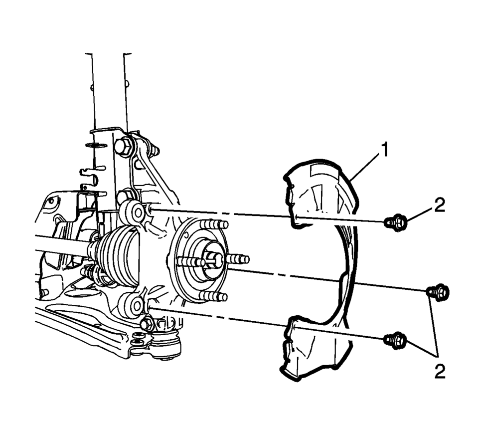
- Remove the front brake dust shield bolts (2) and the shield (1).
- Remove the lower ball joint bolt and nut from the steering knuckle. Refer to Lower Control Arm Replacement.
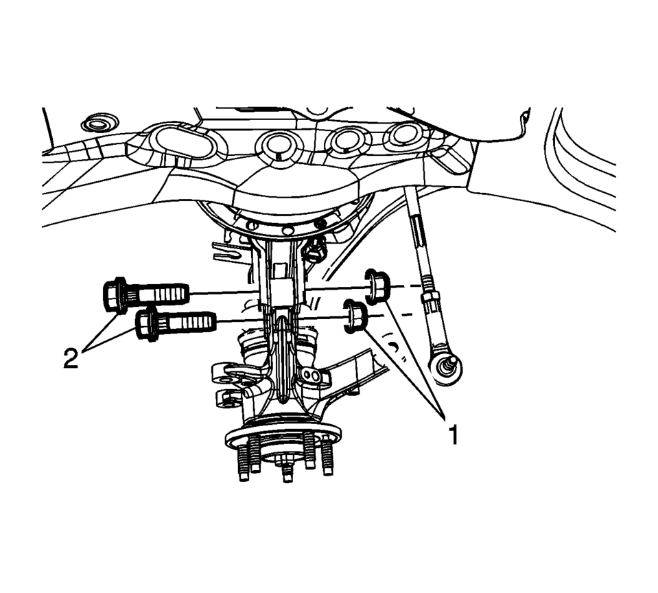
- Remove the bolts (2) and the nuts (1) from the front strut to the steering knuckle. Refer to Strut Assembly Removal and Installation
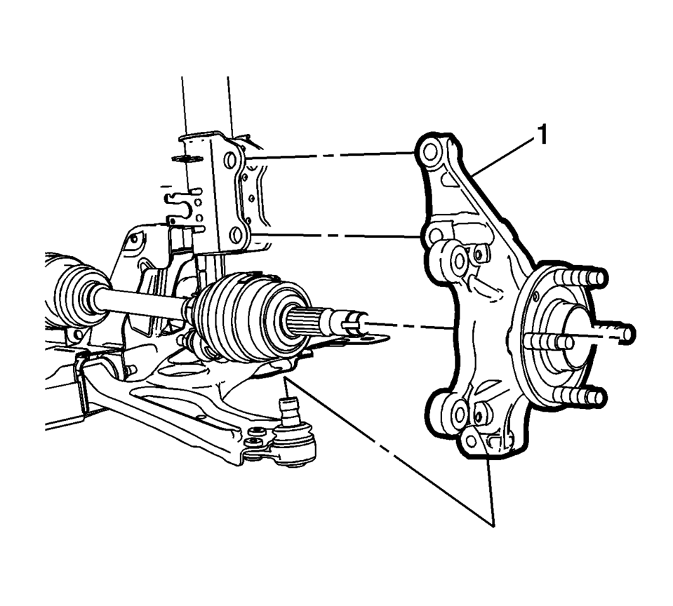
- Remove the steering knuckle assembly (1) from the vehicle.
- Remove the wheel bearing and hub assembly from the steering knuckle. Refer to Front Wheel Bearing and Hub Replacement.
- Installation Procedure
-
- Install the wheel bearing and hub assembly in the steering knuckle. Refer to Front Wheel Bearing and Hub Replacement.
- Position the steering knuckle (1) in the front strut and lower ball joint.
- Install the bolts (2) and the nuts (1) from the front strut assembly to the steering knuckle. Refer to Strut Assembly Removal and Installation.
- Install the lower ball joint bolt and nut to the steering knuckle. Refer to Lower Control Arm Replacement.
- Install the front brake dust shield (1) bolts (2) and the bolts to
9 Y (80 lb in)
.
- Install the brake rotor on the steering knuckle. Refer to Front Brake Rotor Replacement.
- Install the NEW wheel drive shaft nut. Refer to Front Wheel Drive Shaft Replacement.
- Install the wheel speed sensor in the steering knuckle. Refer to Front Wheel Speed Sensor Replacement.
- Install the tire and wheel assembly the tire and wheel assembly. Refer to Tire and Wheel Removal and Installation.
- Remove the supports and lower the vehicle.
- Check the front wheel alignment measurements, if the vehicle had a camber adjustment repair. Refer to Wheel Alignment Specifications.
Caution:
Refer to Fastener Caution.
 Tire and Wheel Assembly-to-Hub/Axle Flange Match-Mounting
Note: After remounting a tire and wheel assembly to a hub/axle flange,
remeasure the tire and wheel assembly on-vehicle runout in order to verify that
the amount of runout has been reduced an ...
 Liftgate Strut Replacement
Liftgate Strut Replacement
Callout
Component Name
1
Liftgate Strut
Warning: When a lift gate hold open device is ...
Other materials:
Braking
Braking action involves perception time and reaction time. Deciding to push the
brake pedal is perception time. Actually doing it is reaction time.
Average driver reaction time is about three-quarters of a second. In that time,
a vehicle moving at 100 km/h (60 mph) travels 20m (66 ft), which co ...
Checking Engine Oil
It is a good idea to check the engine oil level at each fuel fill. In order to
get an accurate reading, the oil must be warm and the vehicle must be on level ground.
The engine oil dipstick handle is a loop. See Engine Compartment Overview for the location of the engine oil dipstick.
1. I ...
Floor Panel Carpet Replacement
Floor Panel Carpet Replacement
Callout
Component Name
Preliminary Procedures
Remove front seats. Refer to Driver or Passenger Seat Removal and
Installation.
Remove rear seat cushion. Refer to Rear Seat Cushion Removal and ...

0.0069