Chevrolet Sonic Repair Manual: Tire Pressure Indicator Sensor Replacement
- Removal Procedure
-
- Raise the vehicle on a suitable support. Refer to Lifting and Jacking the Vehicle.
- Remove the tire/wheel assembly from the vehicle. Refer to Tire and Wheel Removal and Installation.
- Dismount the tire from the rim. Refer to Tire Dismounting and Mounting.
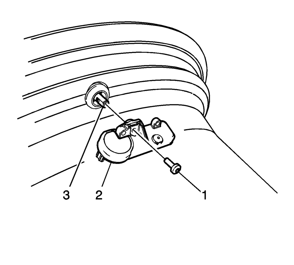
- Remove the TORX screw (1) from the tire pressure sensor (2) and pull it straight off the tire pressure valve stem (3).
- Remove the tire pressure valve stem by pulling it through the rim.
Note:
When servicing the tire pressure sensor always use a new Schrader® tire pressure monitoring (TPM) sensor and a new TORX screw during installation.
Caution:
Do not scratch or damage the clear coating on aluminum wheels with the tire changing equipment. Scratching the clear coating could cause the aluminum wheel to corrode and the clear coating to peel from the wheel.
- Installation Procedure
-
- Ensure the flat of the valve, lines up with the flats of the snap in the enclosure.
- TPM valves and TORX screws are single use items.
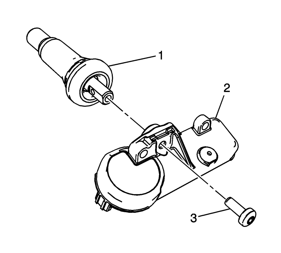
- Assemble the tire pressure sensor (2) to the valve stem and install
the new TORX screw (3), tighten to 1.3 Y (11.5 lb in)
.
- Apply tire soap to the rubber portion of the valve stem (1).
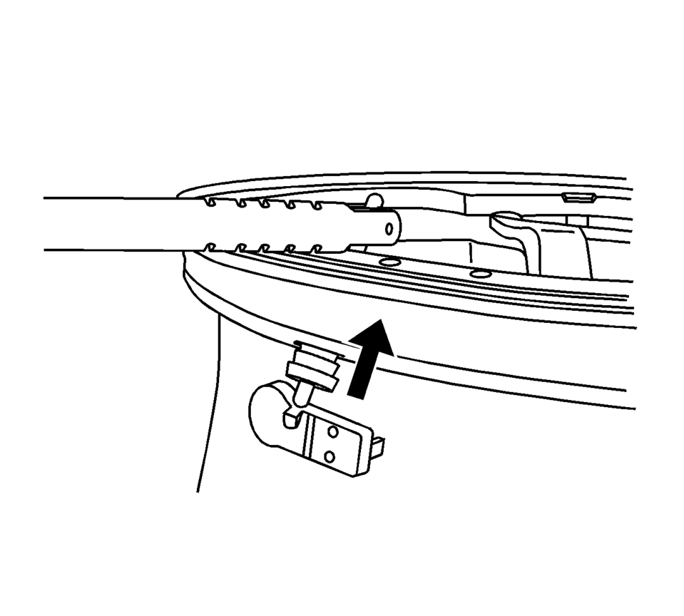
- Using a tire valve stem mounting tool, pull the valve stem through in a direction parallel to the valve hole on the rim.
- Mount the tire to the rim. Refer to Tire Dismounting and Mounting.
- Install the tire/wheel assembly on the vehicle. Refer to Tire and Wheel Removal and Installation.
- Lower the vehicle.
- Learn the tire pressure sensors. Refer to Tire Pressure Indicator Sensor Learn.
Caution:
Refer to Fastener Caution.
Note:
Note:
Use an approved tire mounting lubricant. DO NOT use silicon or corrosive base compounds to lubricate the tire bead and the wheel rim. A corrosive type compound can cause tire or rim deterioration.
Note:
Snap Fit TPM sensors are shipped in the OFF mode. The sensor will exit its OFF state when the tire is inflated.
 Tire Pressure Indicator Sensor Learn
Special Tools
EL-46079 Tire Pressure Monitor Diagnostic Tool
EL-50448 Tire Pressure Monitor Sensor Activation Tool
For equivalent regional tools, refer to Special Tools.
Learn Mode Descr ...
 Tire Pressure Monitor Description and Operation
Tire Pressure Monitoring Block Diagram
...
Other materials:
Brake System External Leak Inspection
Warning: Refer to Brake Fluid Irritant Warning.
Caution: Refer to Brake Fluid Effects on Paint and Electrical Components
Caution.
In order to inspect for external brake fluid leaks, first inspect the fluid
level in the master cylinder.
While a slight brake fluid level drop c ...
Ball Joint Inspection
Caution: Refer to Vehicle Lifting and Jacking Caution.
Raise the front of the vehicle to allow the front suspension to hang free.
Grasp the tire at the top and the bottom.
Move the top of the tire in an in-and-out motion.
Look for any horizontal movement of the knuckle relativ ...
Maintenance schedules
Basic information
To ensure your Nissan Armada delivers reliable performance, optimal safety, and
long-term efficiency, NISSAN provides two distinct maintenance schedules tailored
to different driving conditions. These schedules are carefully designed to cover
both mileage and time intervals, ...

0.0095