Chevrolet Sonic Repair Manual: Tires and Wheels Description and Operation
There are two types of tire and wheel balancing: static and dynamic.
Static balance is the equal distribution of weight around the wheel. Assemblies that are statically unbalanced cause a bouncing action called wheel tramp. This condition may eventually cause uneven tire wear.
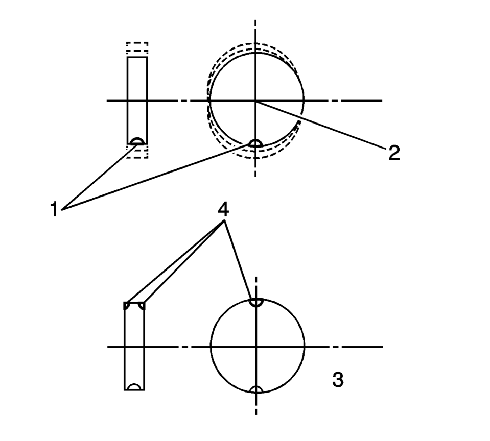
| (1) | Heavy Spot |
| (2) | Centerline of Spindle |
| (3) | Corrective Weights |
| (4) | Add Balance Weights Here |
Dynamic balance is the equal distribution of weight on each side of the centerline so that when the assembly spins there is no tendency for it to move from side to side. Assemblies that are dynamically unbalanced may cause wheel shimmy.
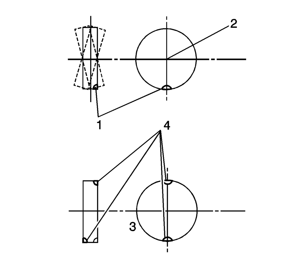
| (1) | Heavy Spot |
| (2) | Centerline of Spindle |
| (3) | Corrective Weights |
| (4) | Add Balance Weights Here |
- General Balance Precautions
-
Remove all deposits of foreign material from the inside of the wheel.
Warning:
Stones should be removed from the tread to provide accurate wheel balancing and to avoid operator injury (from stones becoming dislodged while wheel is in motion) during the procedure.
Inspect the tire for any damage. Balance the tire according to the equipment manufacturer's recommendations.
- Wheel Weights
-
If more than 85 grams (3.0 ounces) are needed to static balance the wheel, split the wheel weights as equally as possible between the inboard and the outboard flanges.
Balancing the assemblies with factory alloy wheels requires the use of special nylon-coated, clip-on wheel weights. These weights are designed to fit over the thicker rim flange of the alloy wheel. Install these weights with a plastic-tipped hammer.
Adhesive wheel weights are also available. Use the following procedure to install adhesive wheel weights
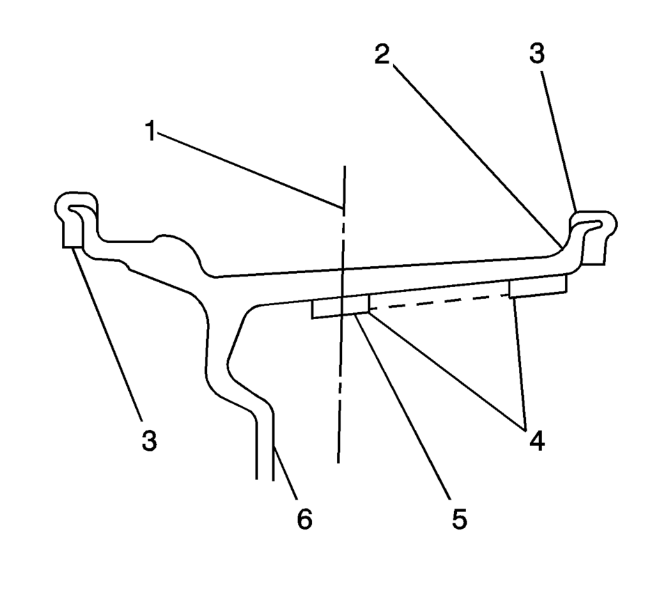
(1) Centerline (2) Inside Flange (3) Clip-on Weight (4) Dynamic Balance Adhesive Weight (5) Static Balance Adhesive Weight (6) Mounting Face
- Adhesive Wheel Weight Installation
-
- Clean the wheel by sanding it to bare alloy where the wheel weight will be installed.
- Use a clean cloth or paper towel saturated with a mixture of half isopropyl alcohol and half water to wipe the place where the wheel weight will be installed.
- Dry the area with hot air. The surface of the wheel should be warm to the touch.
- Warm the adhesive backing on the wheel weights to room temperature.
- Remove the tape from the back of the weights. Do not touch the adhesive surface.
- Apply the wheel weight and press it on with hand pressure
- Secure the wheel weight with a 70-110 N (16-25 lb) force applied with a roller.
- Tire Chain Usage
-
Due to limited tire-to-body clearance on certain vehicles, recommendations for tire chain use are published in the Owner's Manual. When tire chains need to be used, most current General Motors vehicles require SAE Class "S" tire chains. These may also be designated as 1100 Series, type PL tire chains. These chains are specifically designed to limit the "fly off" effect which occurs when the wheel rotates.
Be sure that only fine-link chains are used which do not add more than 15 mm (0.590 in), including the lock, to the tread surface and the inner sides of the tires. Manufacturers of tire chains have a specific chain size for each tire size to ensure a proper fit when the chain is installed. Be sure to purchase the correct chains for the tires on which they are to be used. Use rubber adjusters to take up any slack or clearance in loose chains.
Use of chains may adversely affect vehicle handling. When tire chains are installed, follow these precautions:
- Adjust speed to road conditions
- Avoid sharp turns
- Avoid locked-wheel braking
To prevent chain damage to the vehicle, install the chains on the front tires as tightly as possible. Tighten them again after driving 0.4–0.8 kilometer (0.3–0.5 mile). The use of chains on the rear tires is not recommended because they may contact the vehicle and possibly damage it. If chains must be used on the rear tires, be sure there is sufficient clearance between the chains and the body. Do not exceed 70 km/h (45 mph) or the chain manufacturer's speed limit, if lower. Avoid large bumps, potholes, severe turns and any other maneuvers which could cause the tires to bounce. Follow any other instructions of the chain manufacturer which do not disagree with the above instructions.
 Tire-to-Wheel Match-Mounting (Vectoring)
Note: After remounting a tire to a wheel or after replacing a tire
and/or a wheel, remeasure the tire and wheel assembly runout in order to verify
that the amount of runout has been reduc ...
 Tread Wear Indicators Description
The original equipment tires have tread wear indicators that show when you should
replace the tires.
The location of these indicators are at 60 degree intervals around the outer
diamet ...
Other materials:
Differential Carrier Removal (6T40/45/50)
Differential Carrier Removal
Callout
Component Name
1
Front Differential Carrier Bearing Assembly
2
Differential Carrier Assembly
3
Final Drive Sun Gear
...
Radiator Replacement (LUV)
Removal Procedure
Remove the air cleaner outlet duct. Refer to Air Cleaner Outlet Duct
Replacement.
Remove the front compartment front insulator cover. Refer to Front Compartment
Front Insulator Cover Replacement.
Remove the engine coolant fan shroud. Refer to Engine Coo ...
Ignition Coil Installation
Special Tools
EN-6009 Remover and Installer Ignition Module
For equivalent regional tools, refer to Special Tools.
Install the ignition coil (1) and remove EN-6009 remover and installer
(2).
Caution: Refer to Fastener Caution.
Install the 2 ...

0.0085