Chevrolet Sonic Repair Manual: Camshaft Installation
Special Tools
EN-422 Installer
For equivalent regional tools, refer to Special Tools.
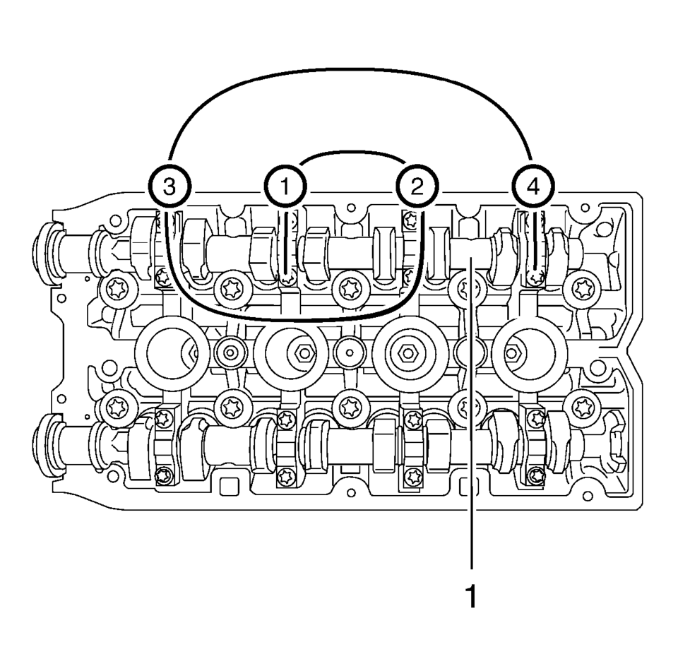
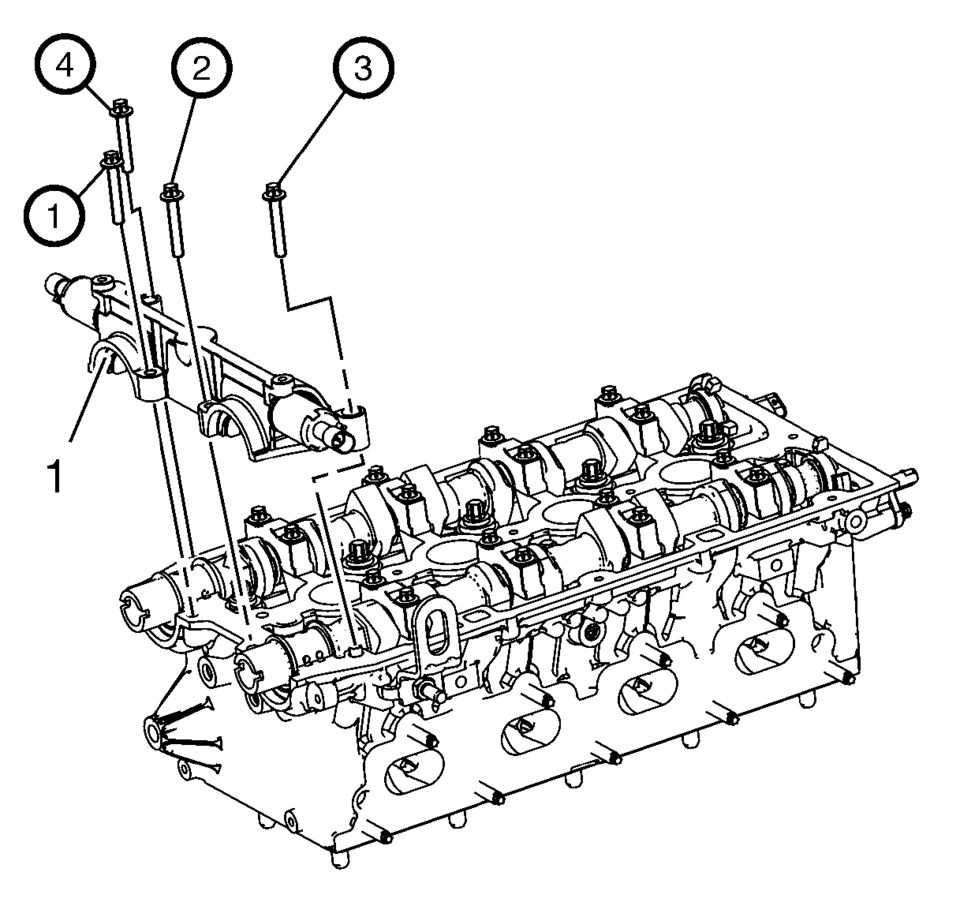
- Install the intake camshaft (1).
- Install the 4 intake camshaft bearing cover number 2-5.
- Install the 8 intake camshaft bearing cover bolts and tighten in a spiral
from the inside to the outside to 8 Y (71 lb in)
.
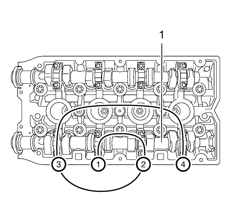
- Install the exhaust camshaft (1).
- Install the 4 exhaust camshaft bearing cover number 6-9.
- Install the 8 exhaust camshaft bearing cover bolts and tighten in a spiral
from the inside to the outside to 8 Y (71 lb in)
.
- Clean sealing surfaces of the first camshaft bearing support and the cylinder
head with a suitable tool.
Clean oil duct from any sealant residue.
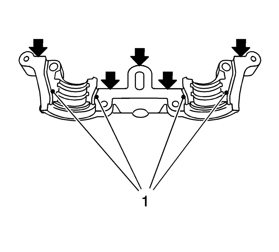
Note:
- Sealing surfaces (arrows) must be free from oil and grease.
- It is essential to ensure that no sealant is applied outside the marked sealing areas (1).
- The grooves adjacent to the sealing surfaces must remain free from sealant.
- Apply surface sealant to sealing surfaces of the first camshaft bearing cap thinly and evenly.
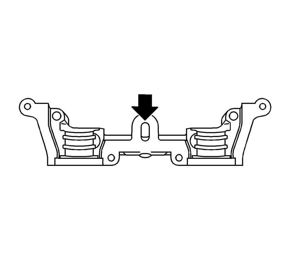
- Position the first camshaft bearing cap on the cylinder block and tighten
the bolts approximately to 2 Y (18 lb in)
.
- Install the first camshaft bearing cap.
- Install the first camshaft bearing cap (1) bolts and tighten to 8 Y (71 lb in)
.
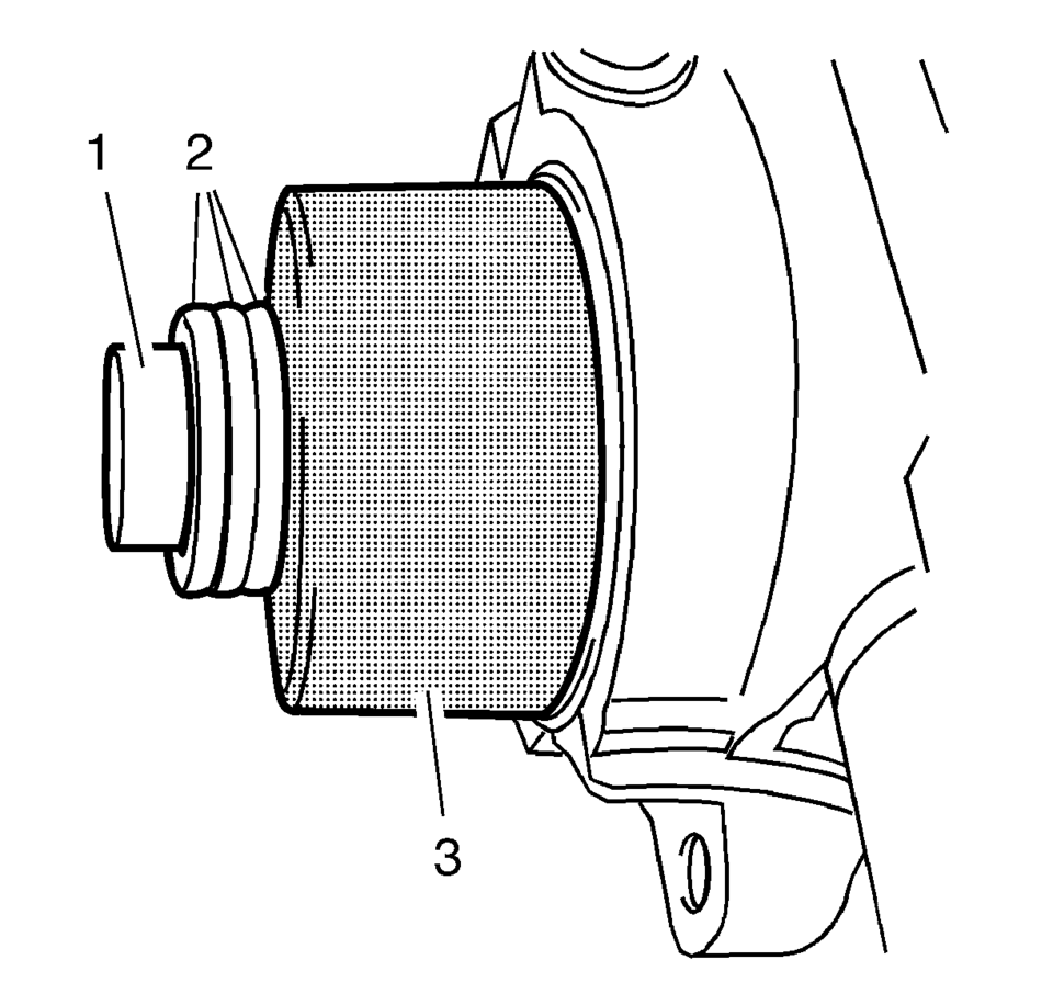
- Install 2 NEW sealing rings to the camshafts.
- Tighten the seal ring with EN-422 installer (3) on the camshaft until this is in contact with the cylinder head.
- To install, use camshaft sprocket bolt (1) in conjunction with shims (2) with a total thickness of approximately 10 mm.
- Remove the EN-422 installer (3).
Note:
Coat with MoS 2 lubricating paste. Refer to Adhesives, Fluids, Lubricants, and Sealers.
Note:
Note the identification marking on the camshaft bearing cover.
Caution:
Refer to Fastener Caution.
Note:
Coat with MoS 2 lubricating paste. Refer to Adhesives, Fluids, Lubricants, and Sealers.
Note:
Note the identification marking on the camshaft bearing cover.
Note:
Sealing surfaces must be free from oil and grease.
Note:
No sealant may reach the camshafts.
Note:
Note installation sequence 1-4.
 Camshaft Cover Replacement
Camshaft Cover Replacement
Callout
Component Name
Preliminary Procedures
Remove the ignition coil. Refer to Ignition Coil Replaceme ...
 Camshaft Intake and Exhaust Sprocket Replacement
Special Tools
EN-955-A Locking Pin
For equivalent regional tools, refer to Special Tools.
Removal Procedure
Remove the air cleaner assembly. Refer to Air Cleaner Assembly Replacemen ...
Other materials:
Front Side Door Weatherstrip Replacement - Door Side
Front Side Door Weatherstrip Replacement - Door Side
Callout
Component Name
1
Front Side Door Weatherstrip Upper Retainer
Procedure
Open the front side door to the fully open position.
Remove the front side do ...
Wheel Stud Replacement
Special Tools
CH 43631 Ball Joint Separator
For equivalent regional tools, refer to Special Tools.
Removal Procedure
Raise and support the vehicle. Refer to Lifting and Jacking the Vehicle.
Remove the tire and wheel assembly. Refer to Tire and Wheel Removal
and In ...
Timing Belt Installation
Special Tools
EN-6333 Locking Pin
EN-6340 Locking Tool
For equivalent regional tools, refer to Special Tools.
Note: The timing belt drive gear and oil pump housing must align.
Turn the crankshaft in the direction of engine rotation, by the crankshaft
balancer bolt ...

0.0055