Chevrolet Sonic Repair Manual: Control Solenoid Valve and Transmission Control Module Assembly Replacement
- Removal Procedure
-
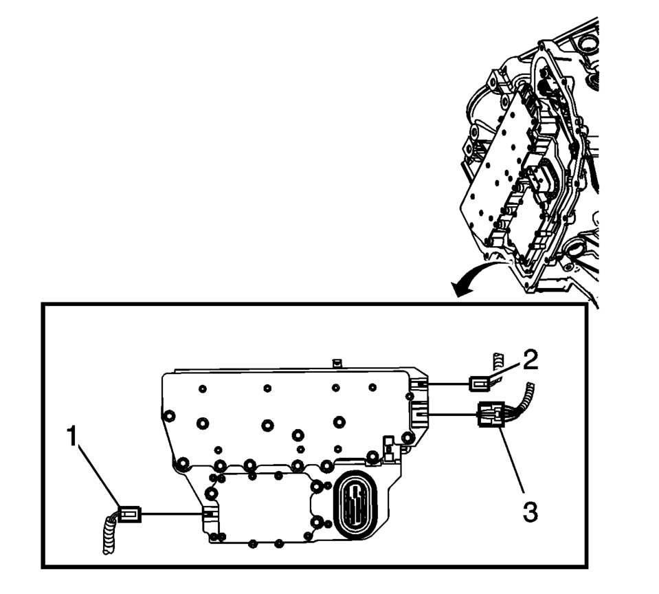
- Remove the transmission control valve body cover. Refer to Control Valve Body Cover Replacement.
- Disconnect the output speed sensor electrical connector (2).
- Disconnect the shift position switch electrical connector (3).
- Disconnect the input speed sensor electrical connector (1).
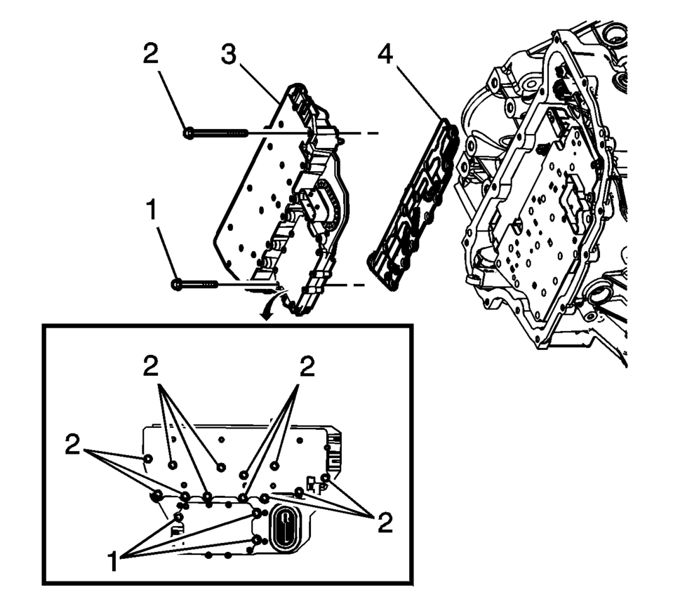
- Remove the 3 control solenoid valve assembly bolts (1) M5 x 40.5.
- Remove the 12 control solenoid valve assembly bolts (2) M6 x 97.
- Remove the control solenoid valve assembly with transmission control module (3).
- Remove the control solenoid valve assembly filter plate (4). Discard the filter plate. It is not reusable.
- Inspect the pressure switch seals for damage or contamination. Replace the control solenoid valve assembly as necessary.
- Inspect the channel plate bolt pass through holes for damage or burnelling. Any damage could cause leaking. Replace as necessary.
Caution:
Use care when removing or installing the filter plate assembly. A broken or missing retaining tab may not adequately secure the filter plate to the control solenoid valve assembly, resulting in possible damage or contamination.
- Installation Procedure
-
- Install a NEW control solenoid valve assembly filter plate (4) to prevent fluid leaks past the fluid seals.
- Install the control solenoid valve assembly with transmission control module (3).
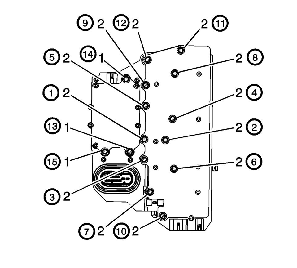
- Hand start the control valve body bolts (1, 2).
- Secure the 12 control solenoid valve assembly bolts (2) M6 x 97
and tighten in sequence to 12 Y (106 lb in)
.
- Secure the 3 control valve body bolts (1) M5 x 40.5
and tighten in sequence to 7 Y (62 lb in)
.
- Connect the input speed sensor electrical connector (1).
- Connect the output speed sensor electrical connector (2).
- Install the transmission control valve body cover. Refer to Control Valve Body Cover Replacement.
- After repairs, refer to Control Module References for programming and set up procedures.
- Perform the transmission adaptive values learn. Refer to Transmission Adaptive Values Learn.
Caution:
Use care when removing or installing the filter plate assembly. A broken or missing retaining tab may not adequately secure the filter plate to the control solenoid valve assembly, resulting in possible damage or contamination.
Caution:
Refer to Fastener Caution.
 Control Solenoid Valve and Transmission Control Module Assembly Programming
and Setup (6T30/6T40/6T45/6T50)
Control Solenoid Valve and Transmission Control Module Assembly Programming
and Setup (6T30/6T40/6T45/6T50)
The following service procedures require either a programming or a setup event
be performed for a complete repair. The transmission control module (TCM) is part
of the control solenoid valve ...
 Transmission Control Lever Boot Replacement
Transmission Control Lever Boot Replacement
Callout
Component Name
Preliminary Procedure
Remove the front floor console. Refer ...
Other materials:
Front Side Door Upper Hinge and Lower Hinge Replacement
Front Side Door Upper Hinge and Lower Hinge Replacement
Callout
Component Name
1
Front Side Door Upper Hinge to Body Bolt (Qty:?€‰2)
Caution: Refer to Fastener Caution.
Procedures
Before removing ...
Passing Assist (ProPILOT Assist 2.1)
Basic information
Passing Assist in the Nissan Armada is an advanced feature of ProPILOT Assist
2.1, engineered to support safer and more efficient overtaking maneuvers on highways.
Before using this function, it is strongly recommended to review the full ProPILOT
Assist section to fully unde ...
Engine oil
Checking engine oil level
Vehicle set-up
To ensure accurate engine oil level readings in your Nissan Armada, follow the
proper preparation steps below.
1. Park the Nissan Armada on a flat, level surface and securely apply the parking
brake.
2. Start the engine and allow it to reach no ...

0.0065