Chevrolet Sonic Repair Manual: Control Valve Body Assembly Installation
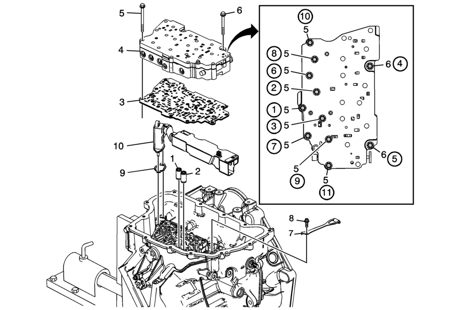
|
Callout |
Component Name |
|---|---|
|
1 |
Low and Reverse Clutch Fluid Passage Seal |
|
2 |
1-2-3-4 Clutch Fluid Passage Seal |
|
3 |
Control Valve Body Spacer Plate Assembly |
|
4 |
Control Valve Body Assembly Note: Align the manual valve to the rod on the manual shaft. |
|
5 |
Control Valve Body Bolt M6 x 60 (Qty: 9) Caution: Refer to Fastener Caution.
11 Y (97 lb in) |
|
6 |
Control Valve Body Bolt M6 x 53 (Qty: 2) Tighten
11 Y (97 lb in) |
|
7 |
Manual Shaft Detent Lever Spring Assembly |
|
8 |
Manual Shaft Detent Spring Bolt M6 x 16 (Qty: 1) Tighten
12 Y (106 lb in) |
|
9 |
Fluid Level Control Valve Gasket |
|
10 |
Fluid Level Control Valve |
 Control Valve Body Assembly Disassemble (Gen 2)
Control Valve Body Assembly Disassemble
Callout
Component Name
1
Control Solenoid Valve Support
2
...
 Control Valve Body Assembly Removal
Table 1:
Control Valve Body Cover Removal
Table 2:
Control Solenoid (With Body and TCM) Valve Assembly
Removal
Table 3:
Control Valve Body Assembly Removal
...
Other materials:
Fuel Tank Filler Door Replacement
Fuel Tank Filler Door Replacement
Callout
Component Name
1
Fuel Tank Filler Door
Procedure
Position the fuel tank filler door to the full open position. Using light
outward sliding pressure on the filler door, ...
Caster Description
Caster is the tilting of the uppermost point of the steering axis either forward
or backward, when viewed from the side of the vehicle. A backward tilt is positive (+)
and a forward tilt is negative (−). Caster influences directional control of the
steering but does not a ...
Body Control System Description and Operation
The body control system consists of the body control module (BCM), communications,
and various input and outputs. Some inputs, outputs and messages require other modules
to interact with the BCM. The BCM also has discrete input and output terminals to
control the vehicle's body functions. ...

0.0058