Chevrolet Sonic Repair Manual: Front Side Door Lock Cylinder Coding (Free Wheeling)
Special Tools
BO-49753 Assembly Tool
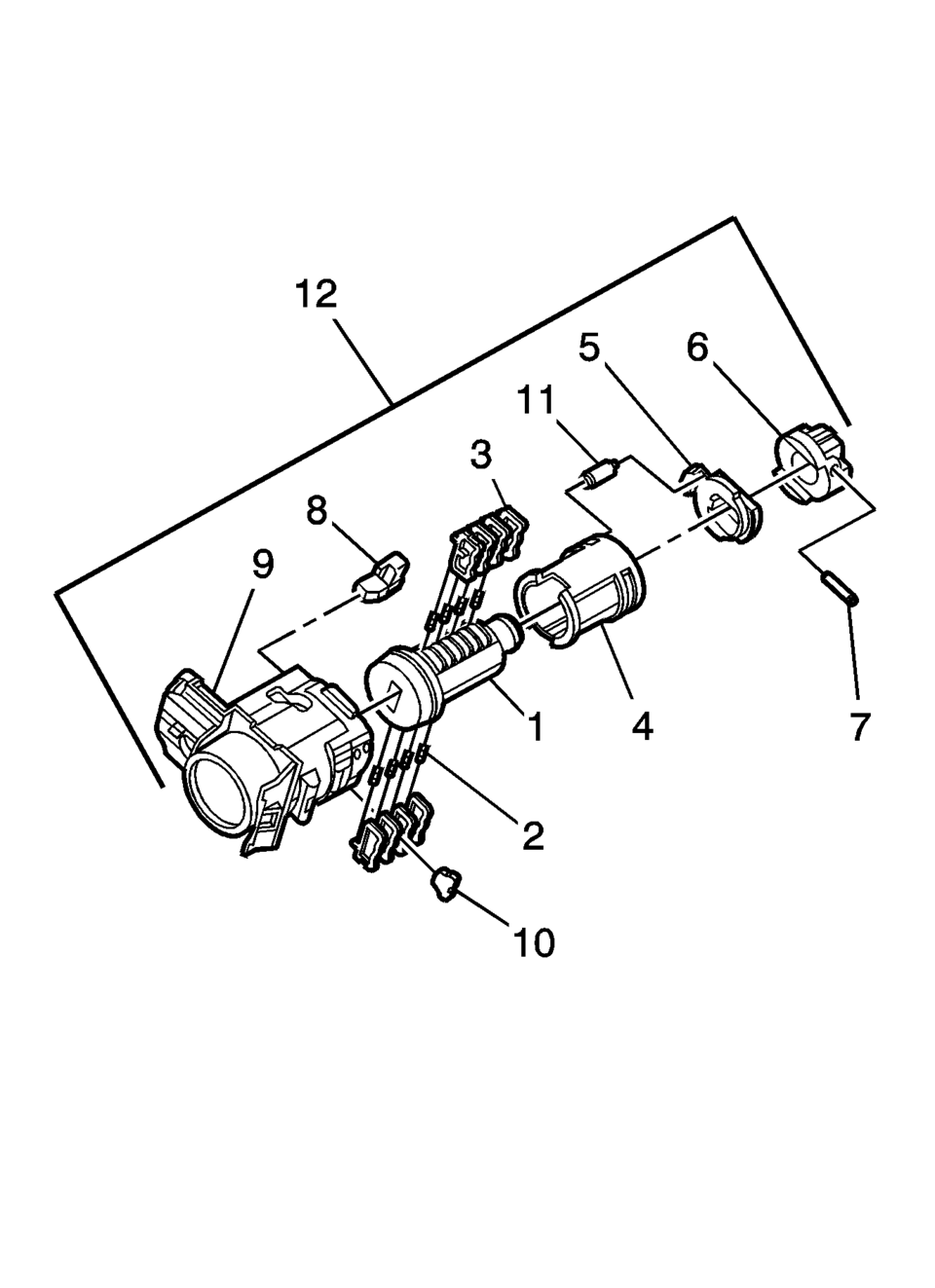
The door lock cylinder uses 8 of the 8?‚ā¨‚Äįcut positions. The tumbler positions are staggered from side to side, 4 on one side and 4 on the other, are not self-retaining, and are not snap in.
- Hold the door lock cylinder?‚ā¨‚Äį(1) so the side with the 4?‚ā¨‚Äįtumbler spring pockets faces up, pocket nearest to the cylinder head.
- Insert the tumbler springs?‚ā¨‚Äį(2) into the 4?‚ā¨‚Äįspring pockets. This side uses left tumblers.
- Install the tumbler?‚ā¨‚Äį(3) for key cut position one in the slot nearest to the front of the lock cylinder. Install the remaining tumblers, key cut positions 3, 5, and 7, following the key code and same process. Press the tumblers in place until they are secure.
- Check the correct loading of the tumblers by inserting the key into the cylinder. All tumblers should be flush with the lock cylinder body.
- Turn the cylinder so the side with the 4?‚ā¨‚Äįtumbler spring wells faces up. This side uses right tumblers.
- Insert the tumbler springs into the 4?‚ā¨‚Äįspring pockets.
- The first tumbler closest to the front of the lock cylinder to be loaded will be the second key cut position, the second number in the key code. Install the remaining tumblers for the key cut positions 4, 6, and 8. Press the tumblers in place until they are secure.
- Check the correct loading of the tumblers by inserting the key into the cylinder. All tumblers should be flush with the lock cylinder body.
- Insert the key and lightly lubricate the cylinder body diameter and tumbler surfaces and a small amount in the head of the cylinder using the supplied grease.
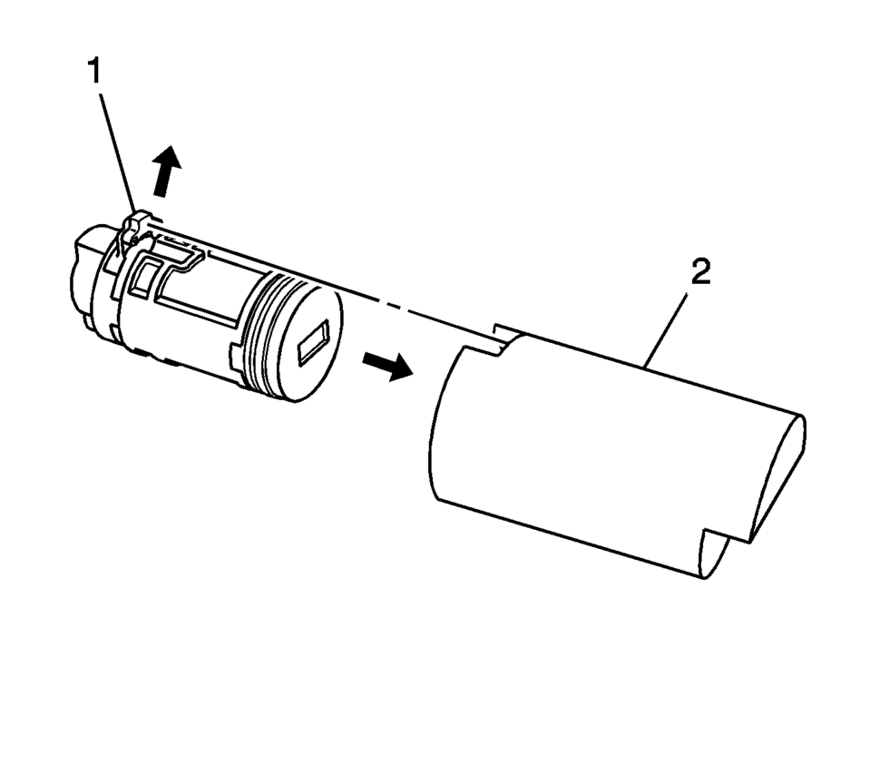
- Insert the sleeve?‚ā¨‚Äį(4) onto the cylinder assembly.
- Insert the clutch?‚ā¨‚Äį(5) and driver?‚ā¨‚Äį(6) onto the cylinder?‚ā¨‚Äį(1).
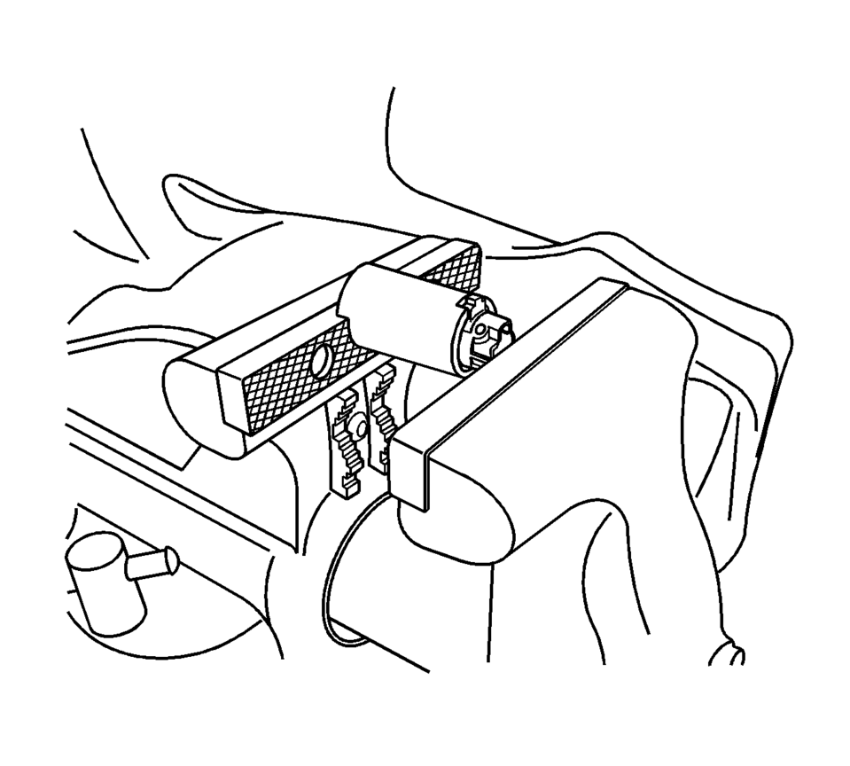
- Load the cylinder into the BO-49753 assembly tool so that the clutch?‚ā¨‚Äį(1) indexes with the notch in the opening of the tool?‚ā¨‚Äį(2).
- Load the assembly tool with the lock cylinder into a vice and tighten the vice ONLY enough to hold the tool and lock the cylinder in place.
- Insert the roll pin?‚ā¨‚Äį(7) into the driver?‚ā¨‚Äį(6) and install it using a 1/16?‚ā¨‚Äįinch pin punch.
- Insert the buffer?‚ā¨‚Äį(8) in the case?‚ā¨‚Äį(9), verify the buffer is properly seated.
- Install the free wheel pin?‚ā¨‚Äį(11) in the sleeve?‚ā¨‚Äį(4) and clutch?‚ā¨‚Äį(5) and insert the assembly into the case?‚ā¨‚Äį(9).
- With the lock cylinder assembly installed in the case?‚ā¨‚Äį(9), install the retainer?‚ā¨‚Äį(10) and stake the retainer in place using a small punch and hammer to peen the case material onto the exposed ends of the installed retainer?‚ā¨‚Äį(10).
- Insert the key into the lock and function the lock to check for proper assembly and smooth operation.
Note:
All lock cylinders for side milled keys have right and left tumblers. The location of the tooth of the tumbler determines whether it is right of left. Illustrations in this procedure show the right tumblers on the top and the left tumblers on the bottom. All tumblers are marked 1R, 1L, 2R, or 2L. The number being cut depth and the letter meaning right or left.
 Front Side Door Check Link Replacement
iii!
Front Side Door Check Link Replacement
Callout
Component Name
Preliminary Procedure
Remove the front side door trim panel. ...
 Front Side Door Lock Cylinder Coding (Non Free Wheeling)
The door lock cylinder uses 8 of the 8?‚ā¨‚Äįcut positions. The tumbler positions
are staggered from side to side, 4 on one side and 4 on the other, are not self-retaining,
and are not snap in ...
Other materials:
Front Side Door Window Switch Bezel Replacement (Left Side)
Front Side Door Window Switch Bezel Replacement
Callout
Component Name
Preliminary Procedure
Remove the front side door trim. Refer to Front Side Door Trim Replacement.
1
Front Side Door Window S ...
Torque Converter Housing with Fluid Pump Assembly Installation (6T40/45/50 Non
Hybrid)
Torque Converter Housing with Fluid Pump Assembly Installation
Callout
Component Name
1
Fluid Pump Seal Assembly
2
Torque Converter Housing Gasket
3
Torque Converte ...
Shift Fork Cleaning and Inspection (Gen 1)
Warning: Wear safety glasses to avoid injury when using compressed
air or any cleaning solvent. Bodily injury may occur if fumes are inhaled
or if skin is exposed to chemicals.
Clean the following components with a suitable solvent.
Air dry all the parts.
3rd and ...

0.0053