Chevrolet Sonic Repair Manual: Front Side Door Lock Cylinder Coding (Non Free Wheeling)
The door lock cylinder uses 8 of the 8?ⲧβÄΑcut positions. The tumbler positions are staggered from side to side, 4 on one side and 4 on the other, are not self-retaining, and are not snap in.
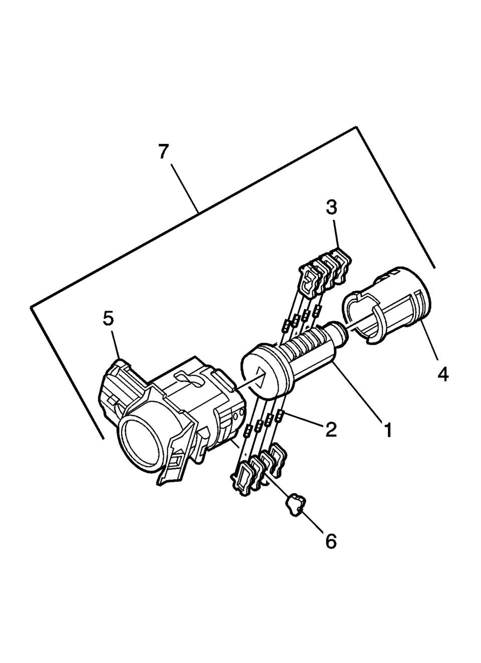
- Hold the door lock cylinder?ⲧβÄΑ(1) so the side with the 4?ⲧβÄΑtumbler spring pockets faces up, pocket nearest to the cylinder head.
- Insert the tumbler springs?ⲧβÄΑ(2) into the 4?ⲧβÄΑspring pockets. This side uses left tumblers.
- Install the tumbler?ⲧβÄΑ(3) for key cut position one in the slot nearest to the front of the lock cylinder. Install the remaining tumblers, key cut positions 3, 5, and 7, following the key code and same process. Press the tumblers in place until they are secure.
- Check the correct loading of the tumblers by inserting the key into the cylinder. All tumblers should be flush with the lock cylinder body.
- Turn the cylinder so the side with the 4?ⲧβÄΑtumbler spring wells faces up. This side uses right tumblers.
- Insert the tumbler springs into the 4?ⲧβÄΑspring pockets.
- The first tumbler closest to the front of the lock cylinder to be loaded will be the second key cut position, the second number in the key code. Install the remaining tumblers for the key cut positions 4, 6, and 8. Press the tumblers in place until they are secure.
- Check the correct loading of the tumblers by inserting the key into the cylinder. All tumblers should be flush with the lock cylinder body.
- Insert the key and lightly lubricate the cylinder body diameter and tumbler surfaces and a small amount in the head of the cylinder using the supplied grease.
- Insert the sleeve?ⲧβÄΑ(4) onto the cylinder assembly.
- Insert the assembly into the case?ⲧβÄΑ(5).
- With the lock cylinder assembly installed in the case?ⲧβÄΑ(5), install the retainer?ⲧβÄΑ(6) and stake the retainer in place using a small punch and hammer to peen the case material onto the exposed ends of the installed retainer?ⲧβÄΑ(6).
- Insert the key into the lock and function the lock to check for proper assembly and smooth operation.
Note:
All lock cylinders for side milled keys have right and left tumblers. The location of the tooth of the tumbler determines whether it is right of left. Illustrations in this procedure show the right tumblers on the top and the left tumblers on the bottom. All tumblers are marked 1R, 1L, 2R, or 2L. The number being cut depth and the letter meaning right or left.
 Front Side Door Lock Cylinder Coding (Free Wheeling)
Special Tools
BO-49753 Assembly Tool
The door lock cylinder uses 8 of the 8?ⲧβÄΑcut positions. The tumbler positions
are staggered from side to side, 4 on one side and 4 on the other, are ...
 Front Side Door Lock Cylinder Opening Cover Replacement
Front Side Door Lock Cylinder Opening Cover Replacement
Callout
Component Name
1
Front Side Door Lock Cylinder Opening C ...
Other materials:
USB Port
The USB Port, if equipped, is in the storage area to the right of the infotainment
system. See Overview (Radio with Touchscreen) or Overview (AM-FM Radio) or Overview (Radio with CD/USB).
Portable devices are controlled by using the menu system described in Operation.
1. 3.5mm (1/8 ...
Sunroof Window Replacement
Sunroof Window Replacement
Callout
Component Name
1
Sunroof Window Bolt?ⲧβÄΑ(Qty:?ⲧβÄΑ4)
Caution: Refer to Fastener Caution.
Tighten
5?ⲧβÄΑY (44?ⲧβÄΑlb?ⲧβÄΑin)
2
...
Basic information
The engine cooling system of the Nissan Armada is factory-filled with a precisely
balanced mixture consisting of 50% Genuine NISSAN Long Life Antifreeze/Coolant (blue)
and 50% water. This formulation ensures reliable year-round protection against freezing,
overheating, and corrosion.
This adv ...

0.0056