Chevrolet Sonic Repair Manual: Intake Manifold Replacement (LDE)
- Removal Procedure
-
- Disconnect the negative battery cable. Refer to Battery Negative Cable Disconnection and Connection.
- Remove the throttle body assembly. Refer to Throttle Body Assembly Replacement.
- Disconnect wiring harness plug.
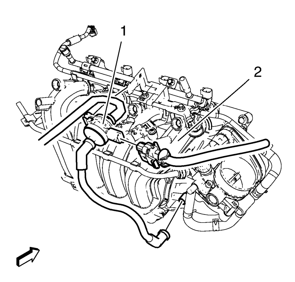
- Disconnect the pipes from the evaporative emission canister purge solenoid valve (1).
- Remove the evaporative emission canister purge solenoid valve (1) and the rubber mounting from the intake manifold (2).
- Disconnect and reposition the electrical connectors as necessary.
- Remove the fuel injector rail. Refer to Fuel Injector Replacement.
- Remove the manifold absolute pressure sensor. Refer to Manifold Absolute Pressure Sensor Replacement.
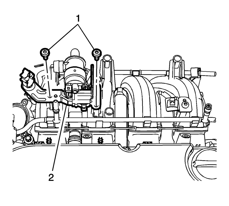
- Remove the evaporative emission canister purge solenoid valve bracket bolts (1).
- Remove the evaporative emission canister purge solenoid valve bracket (2).
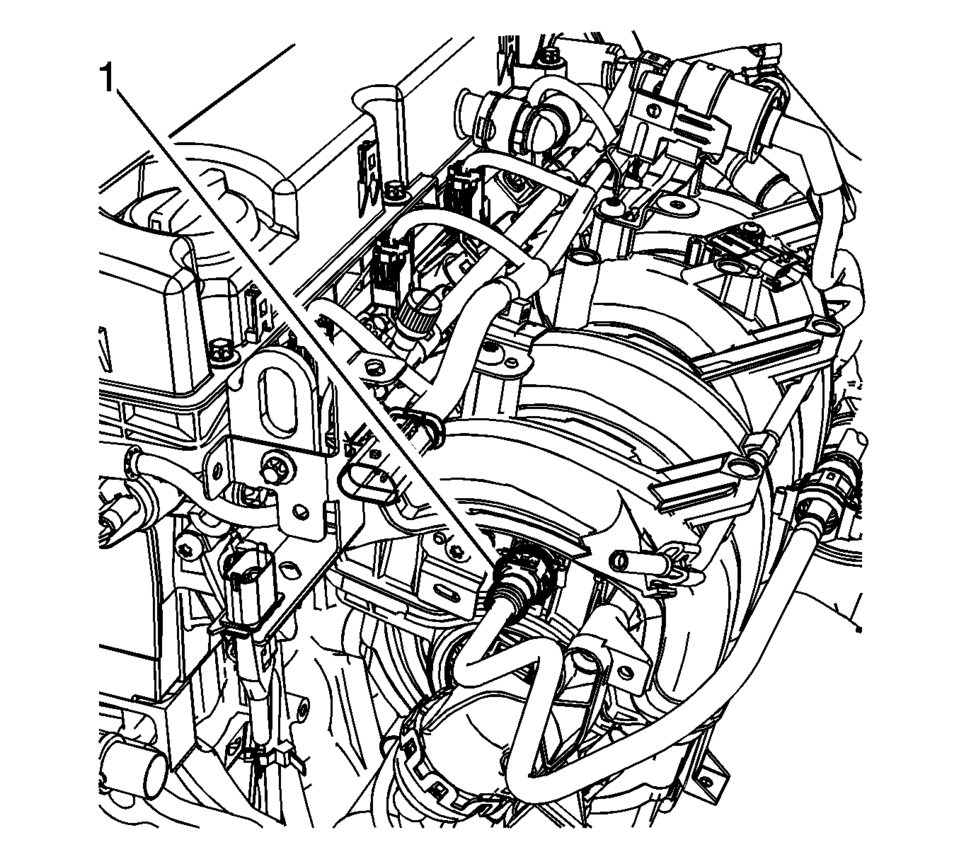
- Disconnect the booster vacuum pipe (1) from the intake manifold.
- Remove the front wheel drive shaft right side. Refer to Front Wheel Drive Shaft Replacement.
- Remove the starter. Refer to Starter Replacement.
- Remove the generator. Refer to Generator Replacement.
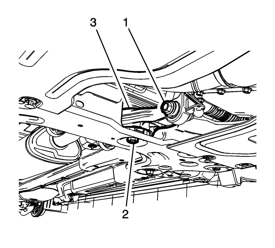
- Remove and DISCARD the transmission rear mount to bracket through bolt (1).
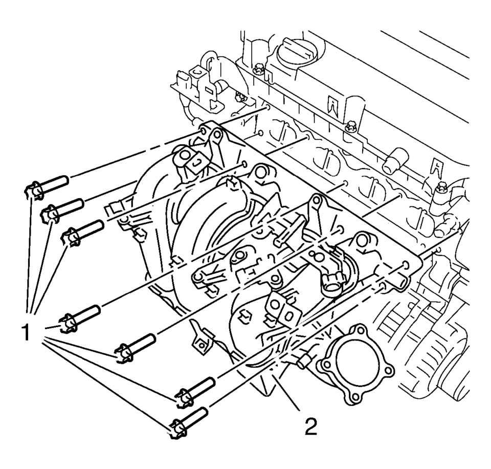
- Remove the intake manifold bolts (1).
- Remove the intake manifold (2).
- Clean and inspect the intake manifold. Refer to Intake Manifold Cleaning and Inspection.
:1
- Installation Procedure
-
- Clean the sealing surfaces.
- Install the NEW gasket.
- Install the intake manifold (2) and the 7 intake manifold bolts (1)
and tighten to 20 Y (15 lb ft)
.
- Install the NEW transmission rear mount to bracket through bolt (1)
and tighten to 80 Y (59 lb ft) plus 45-60 degrees
.
- Install the generator. Refer to Generator Replacement.
- Install the starter. Refer to Starter Replacement.
- Install the front wheel drive shaft right side. Refer to Front Wheel Drive Shaft Replacement.
- Connect the booster vacuum pipe (1) to the intake manifold.
- Install the manifold absolute pressure sensor. Refer to Manifold Absolute Pressure Sensor Replacement.
- Install the evaporative emission canister purge solenoid valve bracket (2).
- Install the evaporative emission canister purge solenoid valve bracket
bolts (1) and tighten to 8 Y (71 lb in)
.
- Connect the electrical connectors as necessary.
- Install the fuel injector rail. Refer to Fuel Injector Replacement.
- Install the evaporative emission canister purge solenoid valve (1) and the rubber mounting to the intake manifold (2).
- Connect the pipes to the evaporative emission canister purge solenoid valve (1).
- Connect wiring harness as necessary.
- Install the throttle body assembly. Refer to Throttle Body Assembly Replacement.
- Connect the negative battery cable. Refer to Battery Negative Cable Disconnection and Connection.
Caution:
Refer to Fastener Caution.
:1
 Intake Manifold Replacement
Special Tools
EN-34730?E1 Pressure Tester
EN-6015 Closure Plugs
For equivalent regional tools, refer to Special Tools
Removal Procedure
Disconnect the battery negative cable. R ...
 Intake Manifold Replacement (LUW)
Removal Procedure
Disconnect the negative battery cable. Refer to Battery Negative Cable
Disconnection and Connection.
Remove the throttle body assembly. Refer to Throttle Body As ...
Other materials:
Climate Control Systems
These climate control systems control the heating, cooling, and ventilation for
the vehicle.
Climate Control System with Heater and Air Conditioning
1. Temperature Control
2. Fan Control
3. Air Delivery Mode Control
4. Driver and Passenger Heated Seats (If Equipped)
5. Air Conditioning
6. ...
Cruise Control
If the vehicle is equipped with cruise control, a speed of about 40 km/h (25
mph) or more can be maintained without keeping your foot on the accelerator. Cruise
control does not work at speeds below 40 km/h (25 mph).
Warning
Cruise control can be dangerous where you cannot drive safely at a st ...
Front Wheel Speed Sensor Replacement
Removal Procedure
Warning: Refer to Brake Dust Warning.
Raise and support the vehicle. Refer to Lifting and Jacking the Vehicle.
Remove the tire and wheel assembly. Refer to Tire and Wheel Removal
and Installation.
Clean the wheel speed sensor mounting area on t ...

0.0088