Chevrolet Sonic Repair Manual: Intake Manifold Replacement
Special Tools
- EN-34730?E1 Pressure Tester
- EN-6015 Closure Plugs
For equivalent regional tools, refer to Special Tools
- Removal Procedure
-
- Disconnect the battery negative cable. Refer to Battery Negative Cable Disconnection and Connection.
- Remove the engine sight shield.
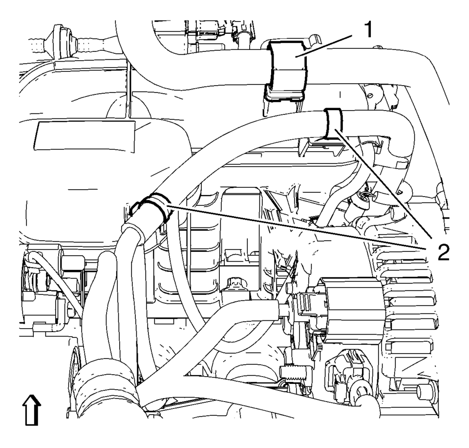
- Unclip the heater outlet hose from retainer clip (1).
- Unclip the engine control module wiring harness from 2 retainer clips (2).
- Lower the vehicle.
- Remove the charge air cooler outlet air hose from the throttle body. Refer to Charge Air Cooler Outlet Air Hose Replacement.
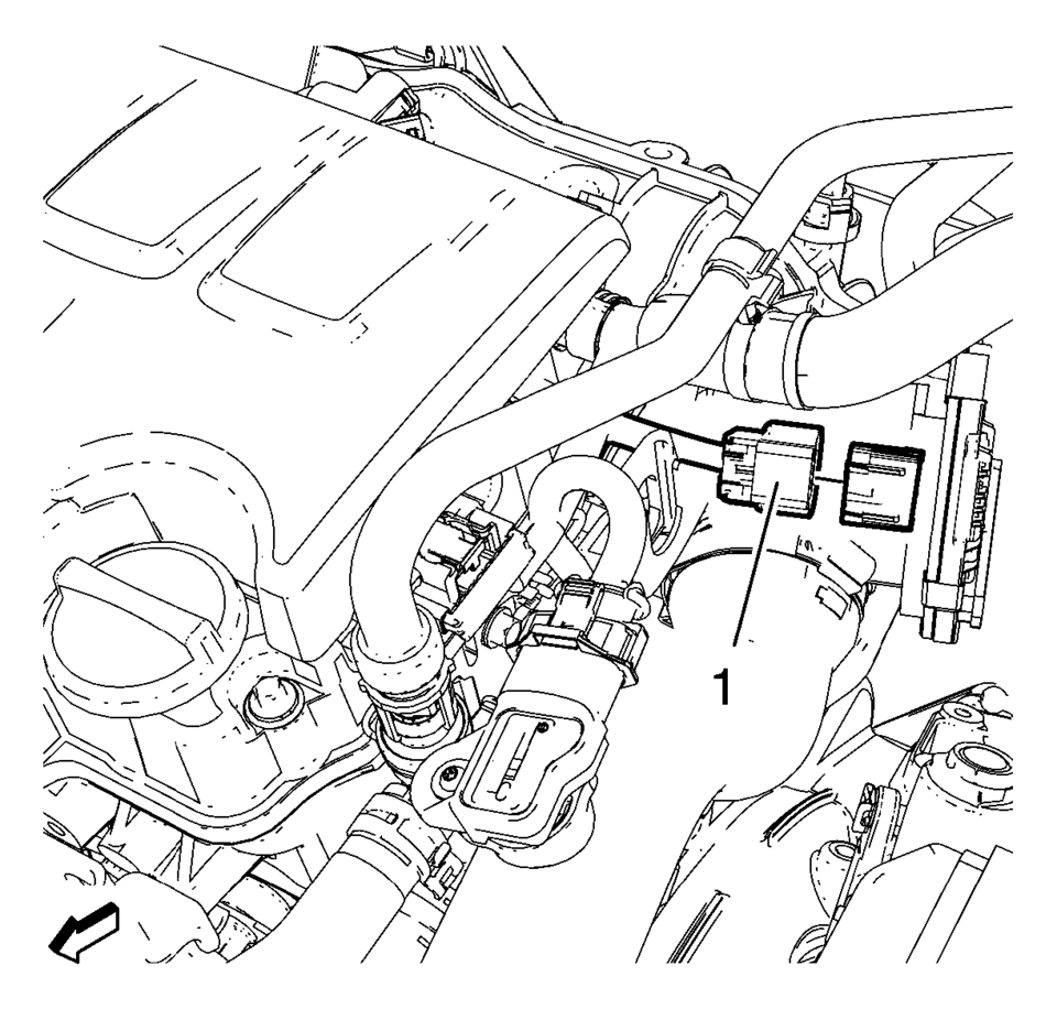
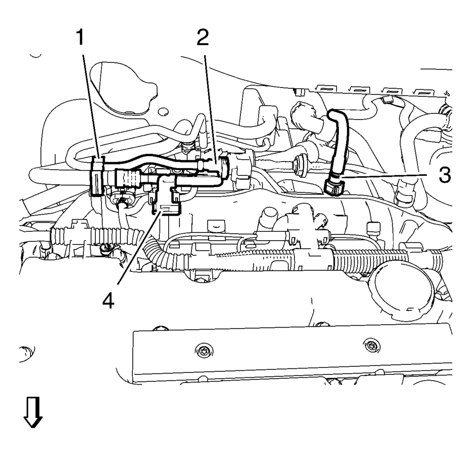
- Disconnect the throttle body wiring harness plug (1).
- Disconnect the evaporative emission canister purge solenoid valve wiring harness plug (2).
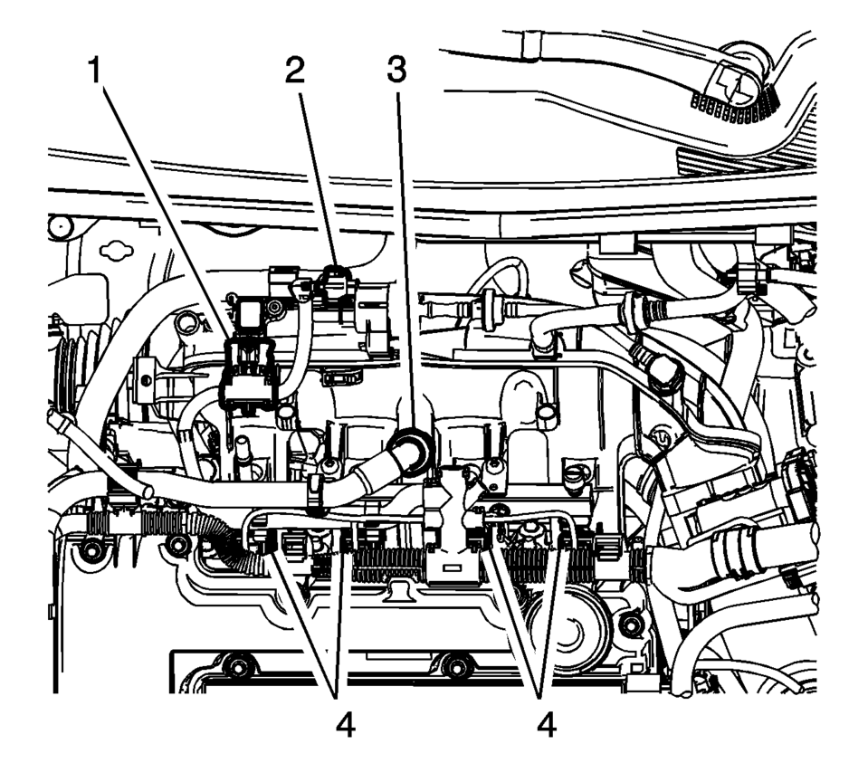
- Disconnect the manifold absolute pressure sensor wiring harness plug (1).
- Disconnect the 4 fuel injector wiring harness plugs (4).
- Unclip the engine control module wiring harness from the camshaft cover.
- Disconnect the PCV hose (3).
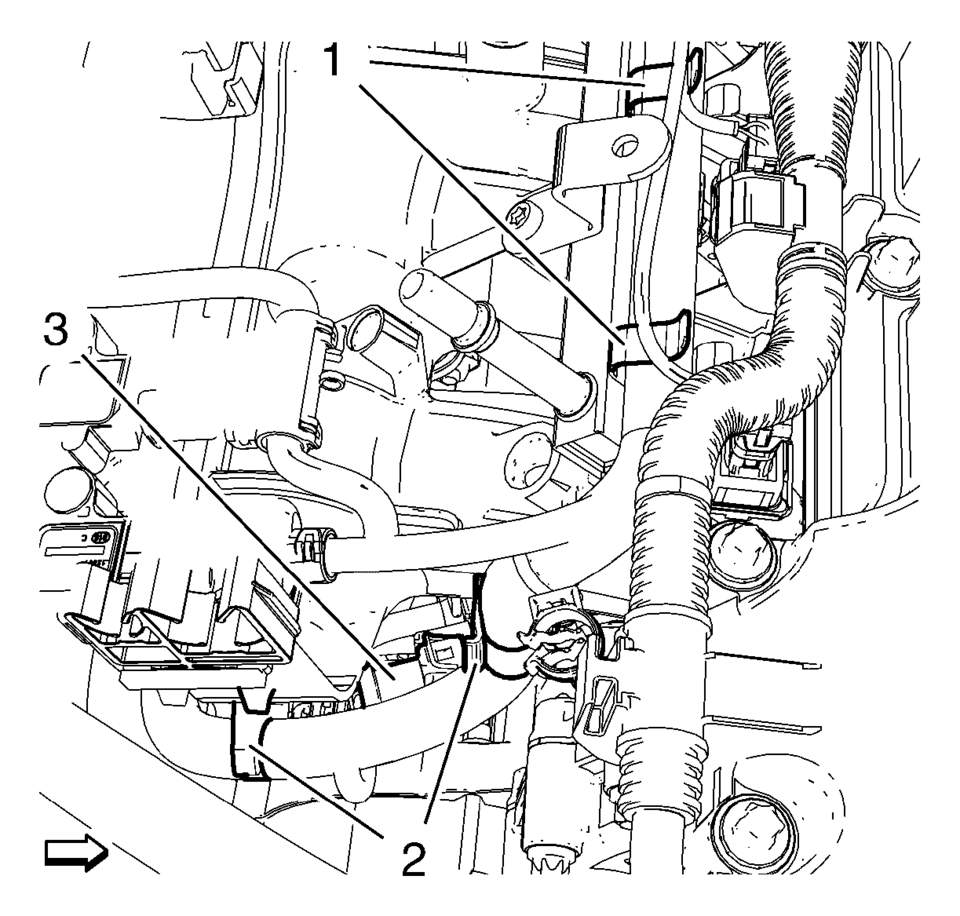
- Disconnect the turbocharger wastegate regulator solenoid valve wiring harness plug (3).
- Unclip the engine control module wiring harness from 2 intake manifold retainer clips (2) and from 2 fuel injection rail retainer clips (1).
- Relieve the fuel system pressure. Refer to Fuel Pressure Relief.
- Remove the fuel feed pipe (4) from fuel injector rail.
- Unclip the fuel feed pipe from retainer clip (1).
- Remove the fuel ventilation pipe (2) from evaporative emission canister purge solenoid valve.
- Unclip the fuel ventilation pipe from retainer clip (1).
- Close the vents with the EN-6015 closure plugs.
- Disconnect the brake booster vacuum pipe (3) from the intake manifold.
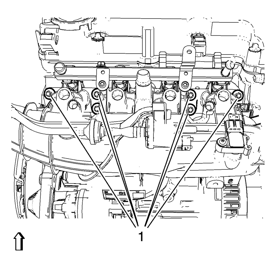
- Remove the 6 intake manifold bolts (1).
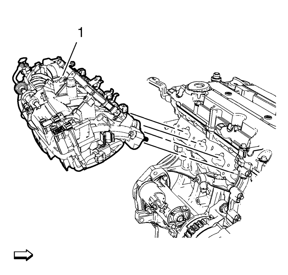
- Remove the intake manifold (1) and the intake manifold gasket.
- Transfer parts from intake manifold as necessary. Refer to Intake Manifold Disassemble and Intake Manifold Assemble.
Note:
The intake manifold bolts remain in intake manifold.
- Installation Procedure
-
- Clean the sealing surfaces.
- Install the intake manifold (1) along with a NEW intake manifold gasket.
- Install the 6 intake manifold bolts (1) and tighten to 20 Y (15 lb ft)
.
- Connect the fuel ventilation pipe (2) to the evaporative emission canister purge solenoid valve.
- Clip in the fuel ventilation pipe to the retainer clip (1).
- Connect the fuel feed pipe (4) to the injector rail.
- Clip in the fuel feed pipe to the retainer clip (1).
- Connect the brake booster vacuum pipe (3) to the intake manifold.
- Connect the turbocharger wastegate regulator solenoid valve wiring harness plug (3).
- Clip in the engine control module wiring harness to 2 intake manifold retainer clips (2) and from 2 fuel injection rail retainer clips (1).
- Clip in the engine control module wiring harness to the camshaft cover.
- Connect the 4 fuel injector wiring harness plugs (4).
- Connect the manifold absolute pressure sensor wiring harness plug (1) .
- Disconnect the evaporative emission canister purge solenoid valve wiring harness plug (2).
- Connect the PCV hose (3).
- Connect the throttle body wiring harness plug (1).
- Install the charge air cooler outlet air hose to the throttle body. Refer to Charge Air Cooler Outlet Air Hose Replacement.
- Raise and support the vehicle.
- Clip in the heater outlet hose to retainer clip (1).
- Clip in the engine control module wiring harness to 2 retainer clips (2).
- Install the engine sight shield.
- Connect the battery negative cable. Refer to Battery Negative Cable Disconnection and Connection.
Caution:
Refer to Fastener Caution.
 Intake Manifold Removal (1.8L LUW and LWE)
Remove the 2 intake manifold brace bolts (2, 3).
Remove the intake manifold brace (1).
Remove the 7 intake manifold bolts (1).
Remove the int ...
 Intake Manifold Replacement (LDE)
Removal Procedure
Disconnect the negative battery cable. Refer to Battery Negative Cable
Disconnection and Connection.
Remove the throttle body assembly. Refer to Throttle Body As ...
Other materials:
Remote Vehicle Start
If equipped, this feature allows the engine to be started from outside the vehicle.
(Remote Vehicle Start): This button
will be on the RKE transmitter if the vehicle has remote start.
The climate control system will use the previous settings during a remote start.
The rear defog may come on d ...
Mobile Telephone Microphone Replacement
Mobile Telephone Microphone Replacement
Callout
Component Name
Preliminary Procedure
Remove the dome lamp bezel. Refer to Dome Lamp
Bezel Replacement.
1
Mobile Telephone Microphone
Procedure ...
Positive Crankcase Ventilation Hose/Pipe/Tube Replacement
Removal Procedure
Remove the air cleaner outlet duct. Refer to Air Cleaner Outlet Duct
Replacement.
Open the 2 positive crankcase ventilation pipe retainer clips (2) and (3).
Note: Move retainer clamp (1) in direction of the arrow. ...

0.0078