Chevrolet Sonic Repair Manual: Timing Belt Replacement
Special Tools
- EN-6333 Timing Belt Tensioner Locking Pin
- EN-6340 Camshaft Locking Tool
For equivalent regional tools, refer to Special Tools.
- Removal Procedure
-
- Remove the air cleaner assembly. Refer to Air Cleaner Assembly Replacement.
- Remove the timing belt upper front cover. Refer to Timing Belt Upper Front Cover Replacement.
- Raise and support the vehicle. Refer to Lifting and Jacking the Vehicle.
- Remove the front wheelhouse liner Inner front extension. Refer to Front Wheelhouse Liner Inner Front Extension Replacement.
- Remove the drive belt tensioner. Refer to Drive Belt Tensioner Replacement.
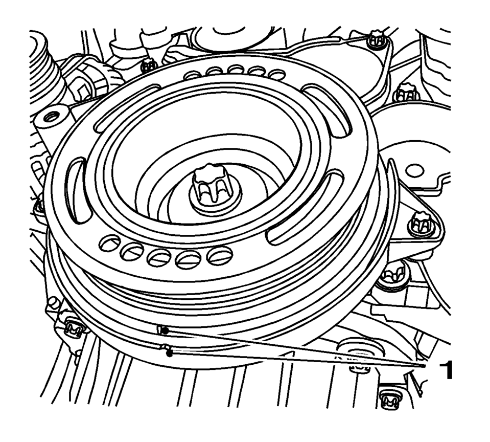
- Set crankshaft balancer in direction of engine rotation to cylinder 1 TDC of combustion stroke (1).
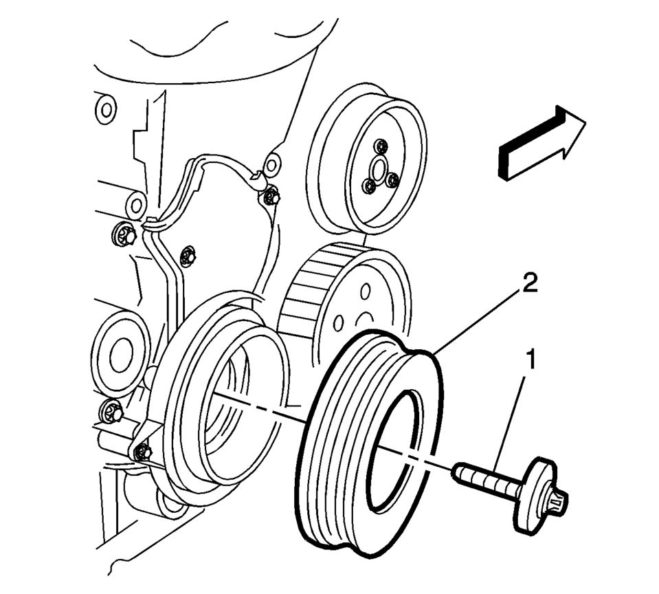
- Remove the crankshaft balancer bolt (1).
- Remove the crankshaft balancer (2). Refer to Crankshaft Balancer Replacement.
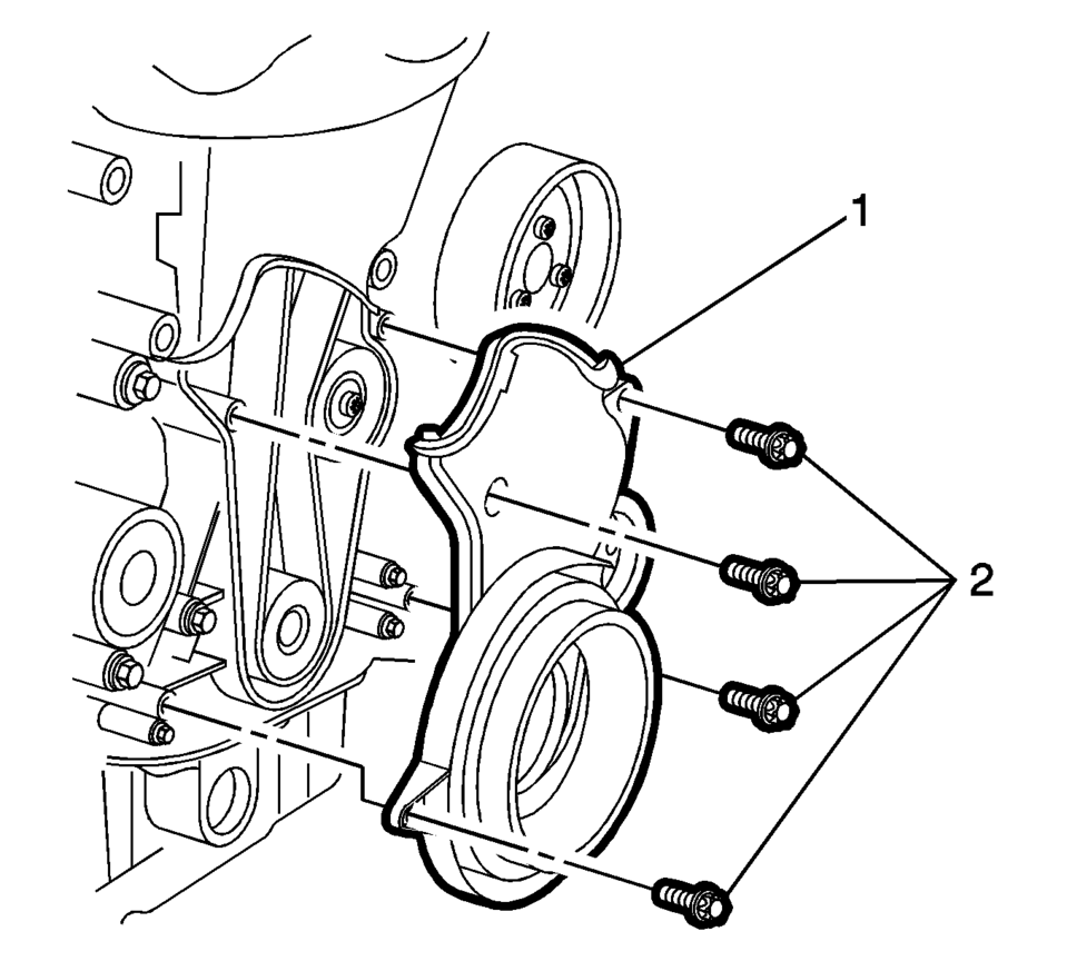
- Remove the 4 lower timing belt cover bolts (2).
- Remove the lower timing belt cover (1).
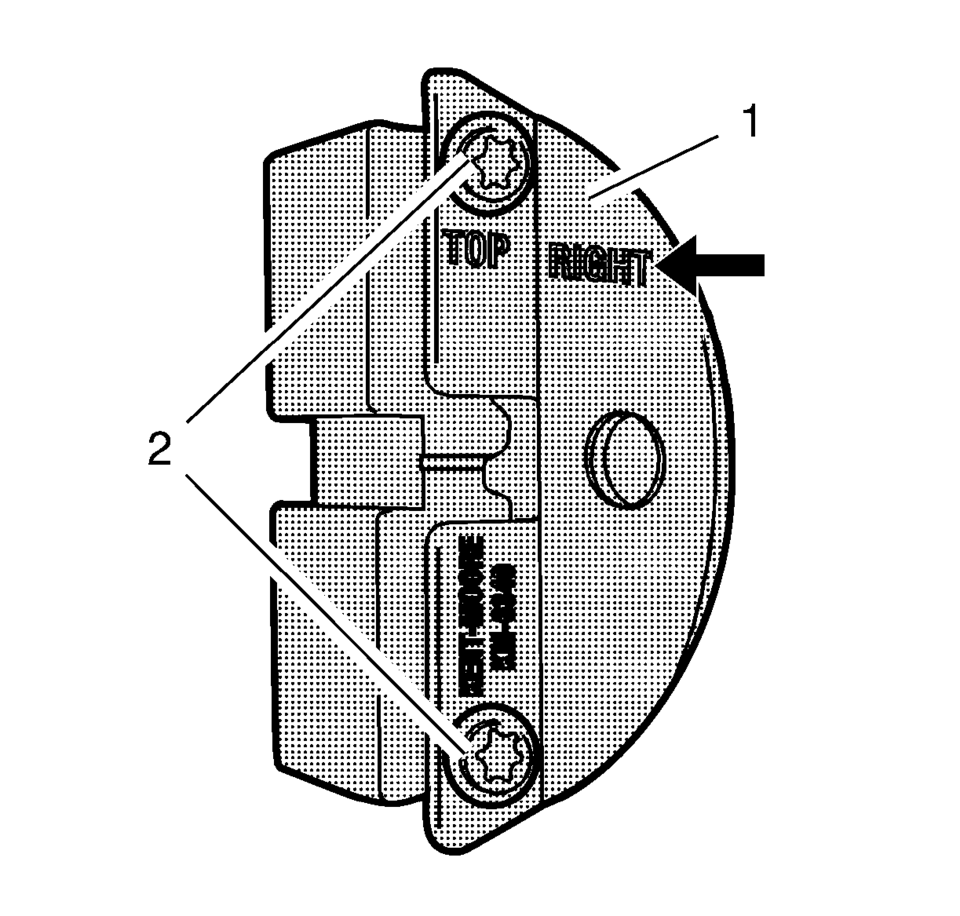
- Prepare the right half of the EN-6340 locking tool.
- Remove the 2 bolts (2).
- Remove the front panel (1) from the EN-6340-right locking tool.
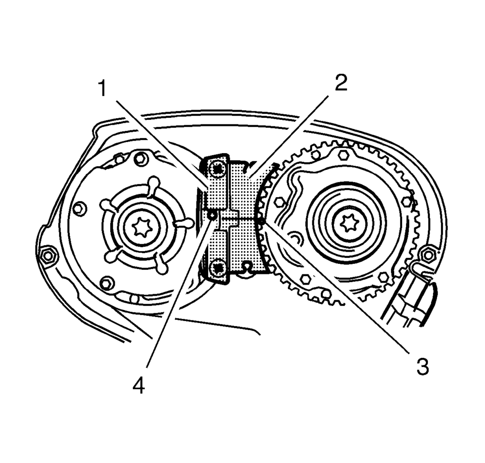
- Install EN-6340 locking tool into the camshaft position actuator adjusters.
- Install EN-6340-left locking tool (1) in the camshaft position actuator adjusters as shown.
- Install EN-6340-right locking tool (2) in the camshaft position actuator adjusters as shown.
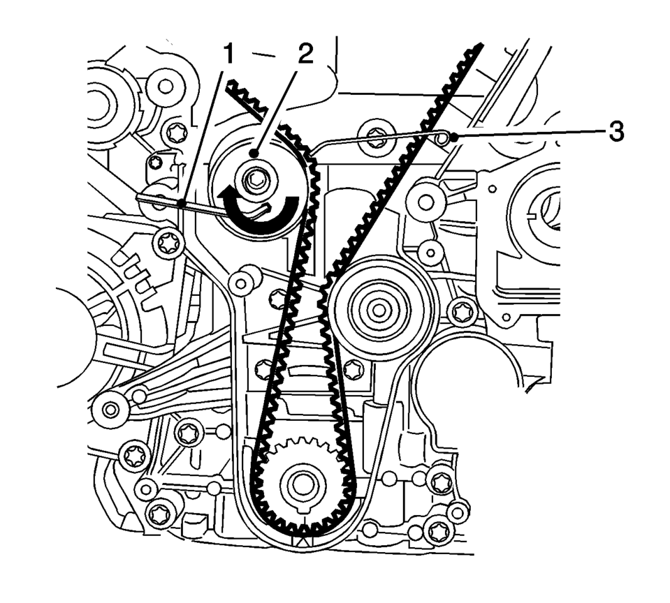
- Apply tension to the timing belt tensioner (2) in the direction of the arrow, using an Allen key (1).
- Install the EN-6333 locking pin(3).
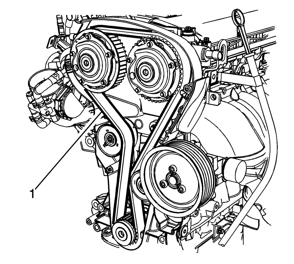
- Remove the timing belt (1).
Note:
If the timing belt is being replaced due to the maintenance schedule interval, then the timing belt tensioner and idler pulley must also be replaced.
((
Note:
The right half of the EN-6340 locking tool can be recognized by the lettering "right", arrow, on the tool.
Note:
The spot type marking (4) on the intake camshaft adjuster does not correspond to the groove of EN-6340-left during this process but must be somewhat above as shown.
Note:
The spot type marking (3) on the exhaust camshaft adjuster must correspond to the groove on EN-6340-right.
Note:
Note the direction of the belt.
- Installation Procedure
-
- Install the timing belt (1).
- Guide the timing belt past the tensioner and place it on the crankshaft sprocket wheel.
- Place the timing belt on the exhaust and intake camshaft position actuator adjusters.
- Apply tension to the timing belt tensioner (2) in the direction of the arrow, using an Allen key (1).
- Remove the EN-6333 locking pin (3).
- Check the timing.
- Turn the crankshaft 720 degrees in the direction of engine rotation by the bolt on the crankshaft balancer.
- Install EN-6340-left locking tool (1) into the camshaft position actuator adjusters as shown.
- Install EN-6340-right locking tool (2) into the camshaft position actuator adjusters as shown.
- Remove the EN-6340 locking tool.
- Control the crankshaft balancer position.
- Install the lower timing belt cover (1).
- Install the 4 lower timing belt cover bolts (2) and tighten to 6 Y
(53 lb in)
.
- Install the crankshaft balancer (2). Refer to Crankshaft Balancer Replacement if necessary.
- Install the crankshaft balancer bolt (1) and tighten to 95 Y (70 lb ft)
plus 30 degrees plus 15 degrees
.
- Install the drive belt tensioner. Refer to Drive Belt Tensioner Replacement.
- Install the front wheelhouse liner Inner front extension. Refer to Front Wheelhouse Liner Inner Front Extension Replacement.
- Install the timing belt upper front cover. Refer to Timing Belt Upper Front Cover Replacement.
- Install the air cleaner assembly. Refer to Air Cleaner Assembly Replacement.
Note:
Threading the timing belt through the engine mount bracket is only permissible in conjunction with the assembly tool supplied with NEW timing belts or otherwise it is possible to damage the toothed belt at this stage by kinking it.
Note:
The timing belt tensioner moves automatically to the correct position.
Note:
Note the marking at the camshaft sprockets.
Note:
The spot type marking (4) on the intake camshaft position actuator adjuster does not correspond to the groove of EN-6340-left during this process but must be slightly above as shown.
Note:
The spot type marking (3) on the exhaust camshaft position actuator adjuster must correspond to the groove on EN-6340-right.

Note:
The timing belt drive gear and oil pump housing must align.
((
Caution:
Refer to Fastener Caution.
 Timing Belt Removal
Special Tools
EN-6333 Locking Pin
EN-6340 Locking Tool
For equivalent regional tools, refer to Special Tools.
Note: The timing belt drive gear and oil pump housing must align.
...
 Timing Belt Upper Front Cover Installation
Install the timing belt upper front cover (1).
Caution: Refer to Fastener Caution.
Install the 2 timing belt upper front cover bolts (2) and tighten to ...
Other materials:
Turning the System On or Off
/VOL (Power/Volume): Press to turn
the system on and off.
Automatic Switch-Off
If the infotainment system is on after the ignition is turned off, the system
will turn off automatically after 10 minutes.
Volume Control
/VOL (Power/Volume): Turn to adjust
the volume.
(Phone/Mute): For ve ...
Tire Inspection
We recommend that the tires, including the spare tire, if the vehicle has one,
be inspected for signs of wear or damage at least once a month.
Replace the tire if:
The indicators at three or more places around the tire can be seen.
There is cord or fabric showing through the tire's rubb ...
Airbag Steering Wheel Module Coil Centering
Note: If a double wire harness strap is installed onto the wire
harness assembly and steering column, the original holder for the wire strap(s)
MUST be reused during installation.
Remove the wire harness strap(s) where necessary.
Caution: The new SIR coil assembly will ...

0.0065