Chevrolet Sonic Repair Manual: Underbody Rear Side Rail Extension Replacement
- Removal Procedure
-
- Disable the SIR System. Refer to SIR Disabling and Enabling.
- Disconnect the negative battery cable. Refer to Battery Negative Cable Disconnection and Connection.
- Remove all related panels and components.
- Visually inspect the damage. Repair as much of the damage as possible.
- Remove the sealers and anti-corrosion materials from the repair area, as necessary. Refer to Anti-Corrosion Treatment and Repair.
- Locate and mark all factory welds.
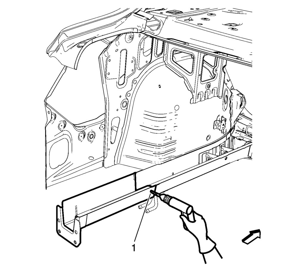
- Drill all factory welds (1). Note the number and location of welds for installation of the service assembly.
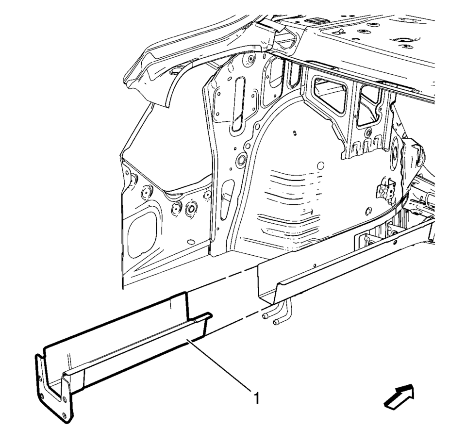
- Remove the damaged rear side rail extension (1).
Warning:
Refer to Approved Equipment for Collision Repair Warning.
Warning:
Refer to Glass and Sheet Metal Handling Warning.
- Installation Procedure
-
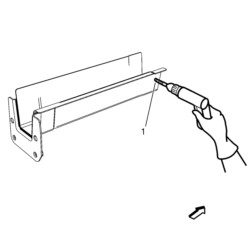
- Drill 8?€‰mm (5/16?€‰in)
holes for plug welding along the edges of the rear side rail extension (1) as noted from the original panel.
- Clean and prepare the attaching surfaces for welding.
- Position the rear side rail extension on the vehicle (1).
- Verify the fit of the rear side rail extension.
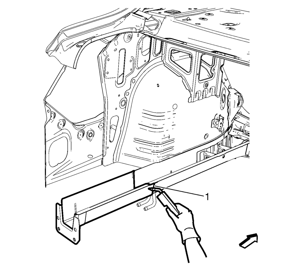
- Clamp the rear side rail extension into position.
- Plug weld accordingly (1).
- Apply the sealers and anti-corrosion materials to the repair area, as necessary. Refer to Anti-Corrosion Treatment and Repair.
- Paint the repaired area. Refer to Basecoat/Clearcoat Paint Systems.
- Install all related panels and components.
- Connect the negative battery cable. Refer to Battery Negative Cable Disconnection and Connection.
- Enable the SIR system. Refer to SIR Disabling and Enabling.
- Drill 8?€‰mm (5/16?€‰in)
 Special Tools
Illustration
Tool Number/ Description
EN-45059
J-45059
Angle Meter
...
 Spoilers/Aero
...
Other materials:
Rear Bumper Impact Bar Replacement (Sedan)
Rear Bumper Impact Bar Replacement
Callout
Component Name
Preliminary Procedure
Remove the rear bumper fascia. Refer to Rear Bumper Fascia Replacement.
1
Rear Bumper Impact Bar Bolt (Qty:?€‰4 ...
Steering Linkage Inner Tie Rod Inspection
Special Tools
GE-8001 Dial Indicator Set
For equivalent regional tools, refer to Special Tools.
Note: This inspection procedure does not supersede local government
required inspections that have more stringent requirements.
Turn the ignition key to the ON position with the eng ...
About microSD card
WARNING
Never allow children to handle or play with the microSD card used in your
Nissan Armada. Due to its small size, accidental swallowing may occur, which can
lead to choking, serious injury, or even life-threatening situations.
NOTE:
If the microSD card is removed from the Nissan Armada ...

0.0057