Chevrolet Sonic Repair Manual: Drive Range, Fifth Gear (Gen 1)
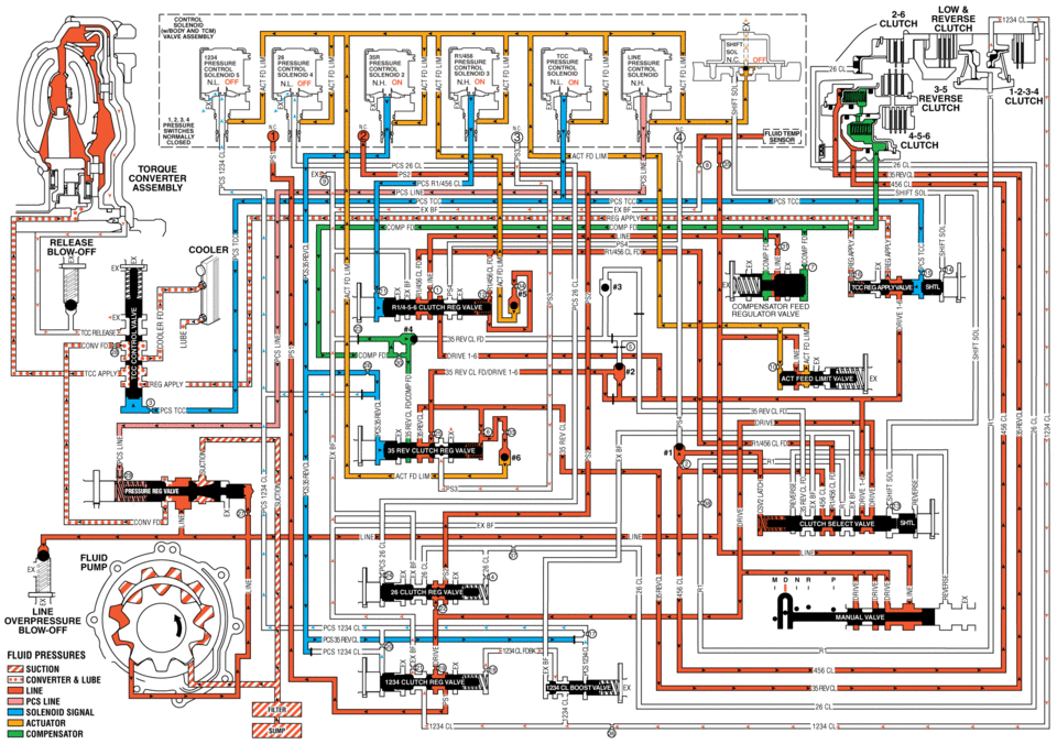
As vehicle speed increases, the transmission control module (TCM) processes input signals from the automatic transmission input and output speed sensors, the throttle position sensor and other vehicle sensors to determine the precise moment to command ON the normally-high 35R pressure control solenoid 2. At the same time, the normally-low 1234 pressure control solenoid 5 is commanded OFF and the transmission shifts into Fifth gear.
- 3-5-Reverse Clutch Applies
-
35R Pressure Control (PC) Solenoid 2
The 35R PC solenoid 2 is commanded ON, allowing actuator feed limit fluid to enter the PCS 35 reverse clutch fluid circuit. PCS 35 reverse clutch fluid is routed through orifice #26 to the 3-5-reverse clutch regulator valve.
3-5-Reverse Clutch Regulator Valve
PCS 35 reverse clutch fluid, at the 3-5-reverse clutch regulator valve, opposes 3-5-reverse clutch regulator valve spring force and 35 reverse clutch feedback fluid pressure to regulate 35 reverse clutch feed/drive 1-6 pressure into the 35 reverse clutch circuit. The 35 reverse clutch fluid is then routed to the 3-5-reverse clutch assembly, through orifice #6 to the spring end of the 3-5-reverse clutch regulator valve and through orifice #33 to the #6 ball check valve. When the 3-5-reverse clutch regulator valve is in this position, PS3 fluid exhausts through the valve allowing the normally-closed #3 pressure switch to close.
3-5-Reverse Clutch
35 reverse clutch fluid enters the 3-5-reverse and 4-5-6 clutch housing assembly to move the 3-5 reverse clutch piston against spring force and compensator feed fluid pressure to apply the 3-5-reverse clutch plates.
#6 Ball Check Valve
35 reverse clutch feed fluid unseats the #6 ball check valve, allowing excess pressure to pass into the actuator feed limit circuit. This helps to control clutch apply fluid pressure and clutch apply feel.
- 1-2-3-4 Clutch Releases
-
1234 Pressure Control (PC) Solenoid 5
The 1234 PC solenoid 5 is commanded OFF, allowing PCS 1234 clutch fluid to exhaust from the 1-2-3-4 clutch regulator valve and the 1-2-3-4 clutch boost valve.
1-2-3-4 Clutch Regulator Valve
1-2-3-4 clutch regulator valve spring force moves the valve to the released position, allowing 1234 clutch fluid pressure from the 1-2-3-4 clutch to pass through the valve and enter the exhaust backfill circuit. The exhausting 1234 clutch fluid pressure is routed through orifice #21 in order to help control the release of the 1-2-3-4 clutch. With the 1-2-3-4 clutch regulator valve in this position, drive fluid passes through the valve into the PS1 circuit. PS1 fluid is routed to the #1 pressure switch and opens the normally-closed switch.
1-2-3-4 Clutch Boost Valve
1-2-3-4 clutch boost valve spring force moves the 1-2-3-4 clutch boost valve to the released position, allowing 1234 clutch feedback fluid pressure to exhaust from the 1-2-3-4 clutch regulator valve into the 1234 clutch circuit.
1-2-3-4 Clutch
1-2-3-4 clutch spring force moves the 1-2-3-4 clutch piston to release the 1-2-3-4 clutch plates and force 1234 clutch fluid to exhaust from the transmission case assembly. The exhausting 1234 clutch fluid is routed to the 1-2-3-4 clutch regulator valve where it enters the exhaust backfill circuit.
- Drive Range, Fifth Gear
low reverse clutch 0f ss ss on: n.h on nh on nl on 3.5 reverse clutch clutch clutch act fd um torque converter cl csm pcs tcc exef ux :xixi: release compensator feed 1-. srevclfd drive rev cl drne ii -lwe overpressure fluid pressures suction converter lube line pcs line solenoid actuator compensatdr cl
 Drive Range - Fourth Gear (Gen 2)
As vehicle speed increases, the transmission control module (TCM) processes input
signals from the automatic transmission input and output speed sensors, the throttle
position sensor and other veh ...
 Drive Range, Fifth Gear (Gen 2)
As vehicle speed increases, the transmission control module (TCM) processes input
signals from the automatic transmission input and output speed sensors, the throttle
position sensor and other veh ...
Other materials:
Liftgate Adjustment
Liftgate Adjustment
Callout
Component Name
1
Liftgate
Caution: Refer to Fastener Caution.
Procedure
Loosen the 4 liftgate hinge bolts to adjust the liftgate.
Adjust the liftgate in order to obtai ...
Front Side Door Weatherstrip Replacement - Door Side
Front Side Door Weatherstrip Replacement - Door Side
Callout
Component Name
1
Front Side Door Weatherstrip Upper Retainer
Procedure
Open the front side door to the fully open position.
Remove the front side do ...
Replacement Wheels Description
Replace the wheel if any of the following conditions exist:
The wheel exhibits excessive runout.
The wheel is bent.
The wheel is cracked.
The wheel is severely rusted.
The wheel is severely corroded.
Note: Air leaks caused by porosity on aluminum wheels are repairable.
...

0.0073