Chevrolet Sonic Repair Manual: Drive Range - Fourth Gear (Gen 2)
As vehicle speed increases, the transmission control module (TCM) processes input signals from the automatic transmission input and output speed sensors, the throttle position sensor and other vehicle sensors to determine the precise moment to command OFF the normally-low 35R pressure control solenoid. At the same time, the normally-high R1/456 pressure control solenoid is commanded ON to regulate 4-5-6 clutch apply and the transmission shifts into Fourth gear.
- 4-5-6 Clutch Applies
-
R1/456 Pressure Control (PC) Solenoid
The R1/456 PC solenoid is commanded ON allowing actuator feed limit fluid to enter the PCS R1/456 clutch fluid circuit. PCS R1/456 clutch fluid is routed through orifice #11 to the R1/4-5-6 clutch regulator valve, and through orifice #34 to the R1/4-5-6 clutch boost valve.
R1/4-5-6 Clutch Regulator Valve
PCS R1/456 clutch fluid, at the R1/4-5-6 clutch regulator valve, opposes R1/4-5-6 clutch regulator valve spring force and orificed R1/456 clutch feed fluid pressure to regulate line pressure into the R1/456 clutch feed circuit. R1/456 clutch feed fluid is then routed to the clutch select valve, the R1/4-5-6 clutch boost valve, and through orifices #9 and #12 to the spring end of the R1/4-5-6 clutch regulator valve. When the R1/4-5-6 clutch regulator valve is in this position, latch fluid exhausts through the valve allowing 456 clutch fluid to shuttle the #1 ball check valve.
R1/4-5-6 Clutch Boost Valve
PCS R1/456 clutch fluid pressure acts on a differential area, moving the R1/4-5-6 clutch boost valve against R1/4-5-6 clutch boost valve spring force, to regulate R1/456 feed clutch fluid into the R1/456 clutch feedback circuit. As PCS R1/456 clutch fluid pressure is increased to a given value, the R1/4-5-6 clutch boost valve opens the R1/456 clutch feedback circuit to exhaust backfill. This results in the R1/4-5-6 clutch regulator valve moving to the full feed position, sending full R1/456 clutch feed pressure (full line pressure) to the 4-5-6 clutch.
#1 Ball Check Valve
Orificed 456 clutch fluid pressure seats the #1 ball check valve against the exhausting latch fluid passage. 456 clutch fluid is then directed into the latch circuit to replace the exhausting latch pressure and is routed to the clutch select valve. Latch fluid combines with clutch select valve spring force and holds the valve in this position during all six forward gear ranges.
Clutch Select Valve
R1/456 clutch feed fluid passes through the clutch select valve and enters the 456 clutch circuit. 456 clutch fluid is routed to the 4-5-6 clutch assembly, and through orifice #2 to the #1 ball check valve.
4-5-6 Clutch
456 clutch fluid enters the 3-5-reverse and 4-5-6 clutch housing assembly, and moves the 4-5-6 clutch piston against spring force and exhaust backfill pressure to apply the 4-5-6 clutch plates.
Accumulator
PCS R1/456 clutch fluid is also routed to an accumulator valve. The accumulator valve is used to dampen any pressure irregularities occurring in the PCS R1/456 clutch fluid circuit. This helps to control clutch apply fluid pressure and clutch apply feel.
- 3-5-Reverse Clutch Releases
-
35R Pressure Control (PC) Solenoid
The 35R PC solenoid is commanded OFF allowing PCS 35 reverse clutch fluid from the 3-5-reverse clutch regulator valve to exhaust.
3-5-Reverse Clutch Regulator Valve
PCS 35 reverse clutch fluid exhausts, allowing 3-5-reverse clutch regulator valve spring force to move the 3-5-reverse clutch regulator valve to the released position. This allows exhausting 35 reverse clutch fluid pressure to pass into the exhaust backfill circuit in order to assist the 3-5-reverse clutch piston spring to quickly release the 3-5-reverse clutch.
3-5-Reverse Clutch
3-5-reverse clutch spring force, assisted by exhaust backfill pressure, moves the 3-5-reverse clutch piston to release the 3-5-reverse clutch plates and force 35 reverse clutch fluid to exhaust from the 3-5-reverse and 4-5-6 clutch housing assembly. The exhausting 35 reverse clutch fluid pressure is routed to the 3-5-reverse clutch regulator valve where it enters the exhaust backfill feed circuit.
- Torque Converter Clutch (TCC) Applies
-
Torque Converter Clutch (TCC) Pressure Control (PC) Solenoid
The TCC PC solenoid is commanded ON, allowing actuator feed limit fluid to enter the PCS TCC fluid circuit. PCS TCC fluid is routed through orifice #15 to the TCC regulator apply valve and through orifice #3 to the TCC control valve.
TCC Regulator Apply Valve
PCS TCC fluid, at the TCC regulator apply valve, opposes TCC regulator apply valve spring force and orificed regulated apply fluid pressure to regulate drive 1-6 fluid into the regulated apply circuit. Regulated apply fluid is routed to the TCC control valve and through orifice #16 to the spring end of the TCC regulator apply valve.
TCC Control Valve
PCS TCC fluid moves the TCC control valve against TCC control valve spring force, allowing regulated apply fluid to pass through the valve into the TCC apply fluid circuit and apply the torque converter clutch. Converter feed fluid passes through orifice #28 to the TCC control valve, replacing TCC apply fluid, to supply the cooler feed circuit. TCC release fluid passes through the TCC control valve and is exhausted.
- Drive Range, Fourth Gear ?#8201;Gen 2/Hybrid
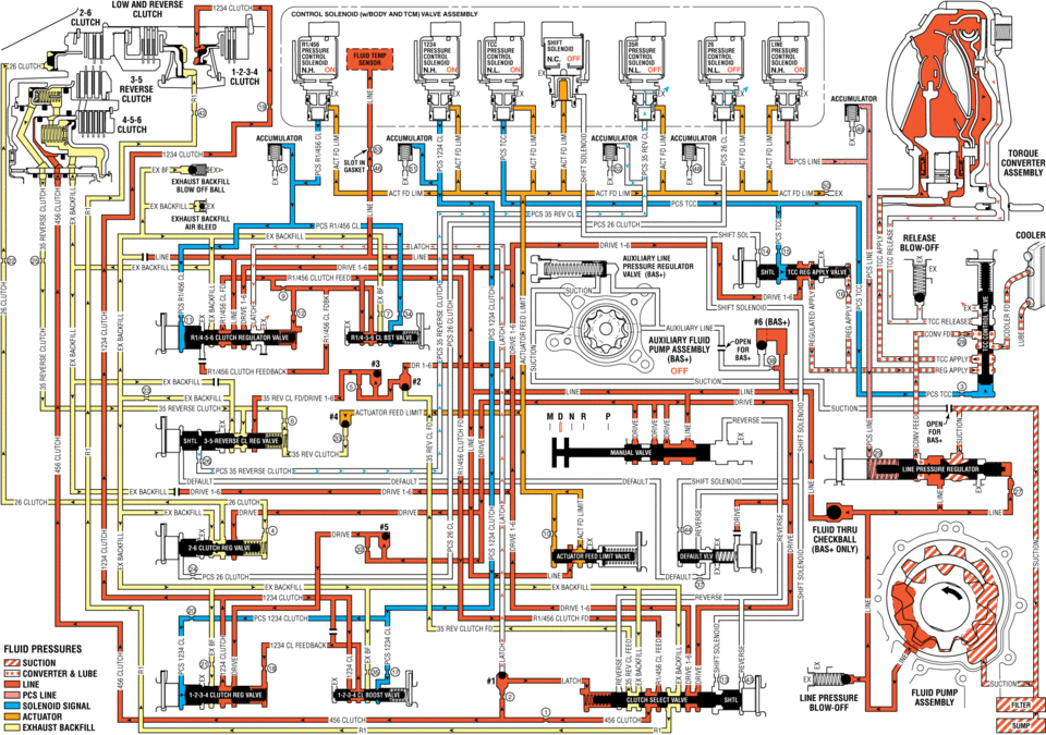
clutch clutch exnaust solenl1ld(wlbijdv valve assembly ex line pcs cl ex ex mus pne press pressure cuumm cnnmm cum cnmm n.l-1. un on on off ace umnlatur pcs 35 cl act fd tdrdue arr am. .. ex exnaust backfill air aleeu release == blow-off ex backhll :. auxiliary fluid feedback off ex ii sucnuu rev cl reverse clutch feed sun 35reilerseelree ..... 35 rev clutch pcs reverse default sulenoid :ex drive fluid nmu checkball pcs 2e une default ex ex backhll reverse v= fluid pnessunes .. suction in converter lube line pcs line solenoid signal actuator exhaust valve clutch line pressure blow-dff converter
 Drive Range - Fourth Gear (Gen 1)
As vehicle speed increases, the transmission control module (TCM) processes input
signals from the automatic transmission input and output speed sensors, the throttle
position sensor and other veh ...
 Drive Range, Fifth Gear (Gen 1)
As vehicle speed increases, the transmission control module (TCM) processes input
signals from the automatic transmission input and output speed sensors, the throttle
position sensor and other veh ...
Other materials:
Front Side Door Upper Hinge and Lower Hinge Replacement
Front Side Door Upper Hinge and Lower Hinge Replacement
Callout
Component Name
1
Front Side Door Upper Hinge to Body Bolt (Qty:?€‰2)
Caution: Refer to Fastener Caution.
Procedures
Before removing ...
Front Wheel Drive Shaft Seal Replacement - Left Side
Front Wheel Drive Shaft Seal Replacement - Left Side
Callout
Component Name
Preliminary Procedure
Raise and support the vehicle. Refer to Lifting and Jacking the
Vehicle.
Remove the front wheel drive shaft from the transm ...
Emergency Call (SOS) button
Emergency support
Basic information
In the Nissan Armada, NissanConnect Services provide a comprehensive range of
emergency assistance features designed to support both the driver and passengers
in critical situations.
For instance, in the event of illness, injury, or any emergency scenario, ...

0.0062