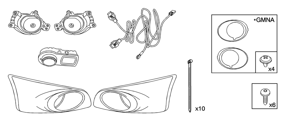
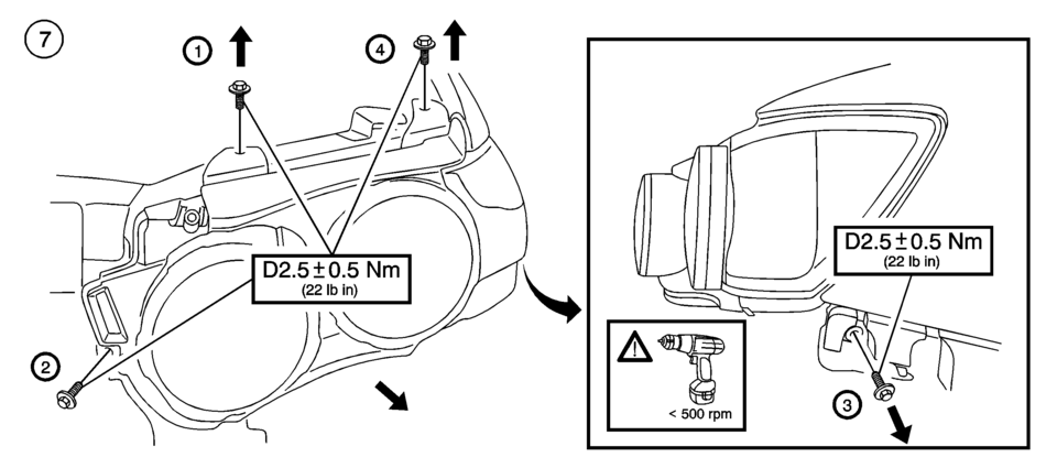
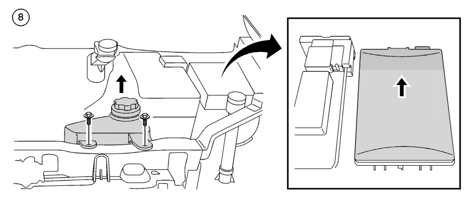
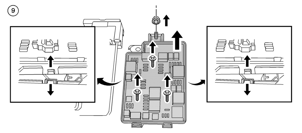
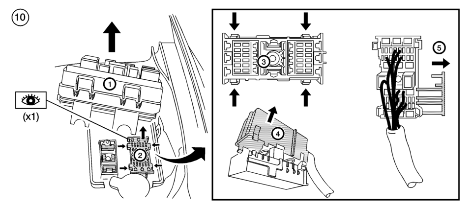
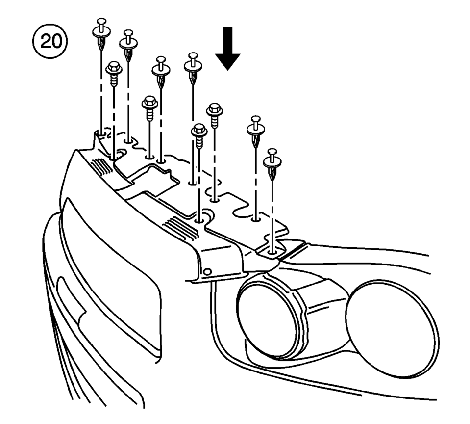
Chevrolet Sonic Repair Manual: Front Fog Lamp Package Installation
- Installation Instructions Part Number
-
95950443

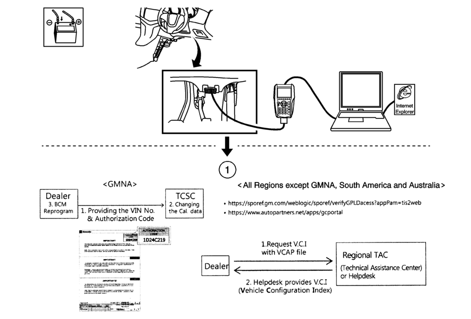
- BCM Programming
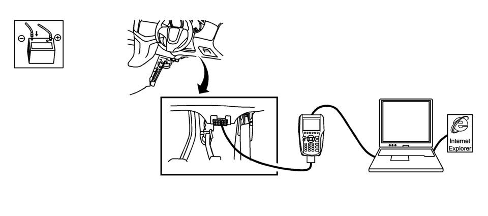
Vehicles are required to update the BCM programming through TIS2Web SPS
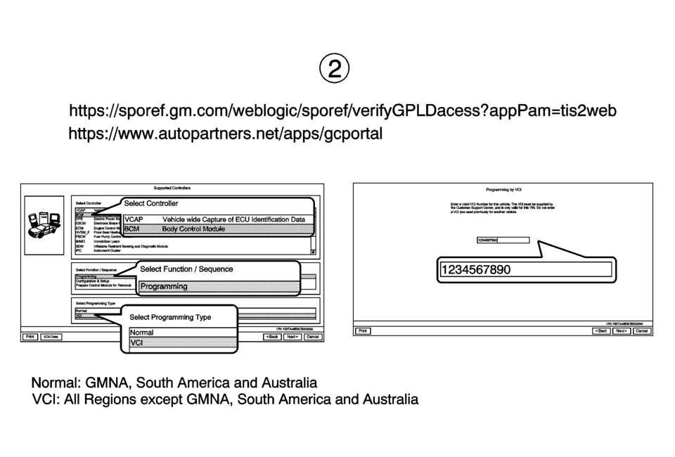
Vehicle Configuration Index- Request V.C.I (Vehicle Configuration Index) for correct BCM reprogram with Front Fog Lamp Variant.
- Select “VCAP” in Select Controller menu in TIS2Web and click “Next”.
- Select “Next”.
- Check “Vehicle wide Capture of ECU Identification Data” and click “Next”.
- The path and filename is set automatically. Click “Next”.
- Now the function is running.
- After the message “Successfully completed, press finish” comes up, click “Finish”. The created XML file (see path) Dealer to send responsible Technical Assistance Center (or Help desk).
- Click “Finish”.
- Click “Finish” to end the function.
Note:
Steps 1 to 9 are for all regions except GMNA, South America and Australia.
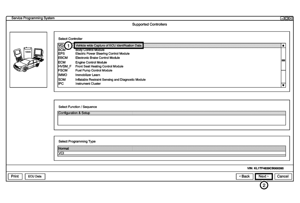
service programming system supported controllers select controller oy onro oue eps electric power steering control module ebcm electronic brake control module ecm engine control module hvsm_f front seat heating control module fscm fuel pump control module immo immobilizer learn sdm inatable restraint sensing and diagnostic module ipc instrument cluster select function sequence select programming type vm: kl1tf4639cb00o395 ecu data <back cancel
Note:
Obtain VCAP file about T300 vehicle which Front Fog Lamp is installed newly.
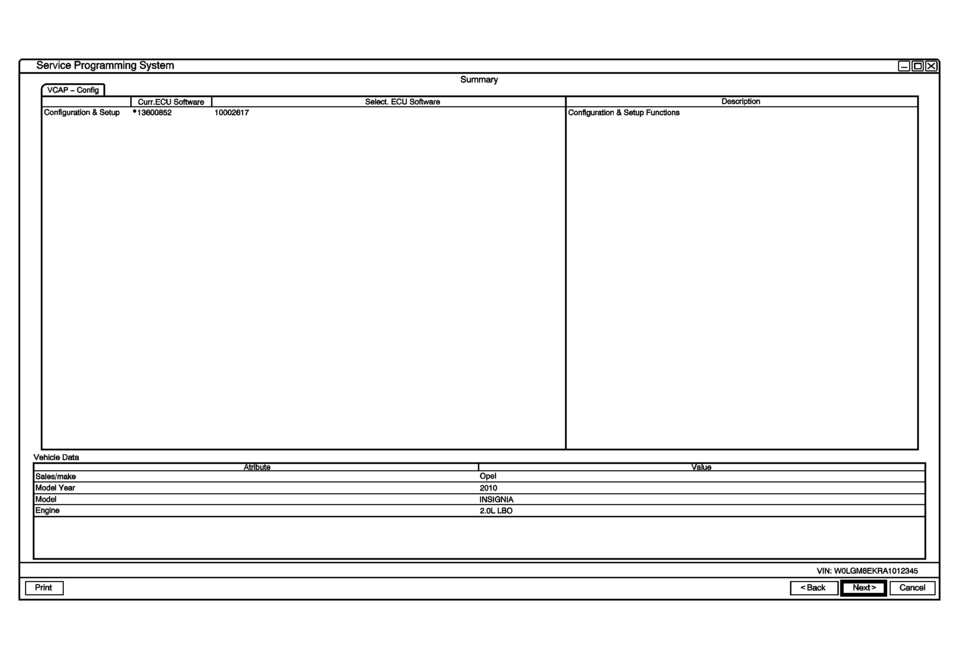
service programming system vgap config curr-ecu software select ecu conguration setup 13600852 10002617 conguration setup funcons vehicle data sales/make opel model year 2010 model insignia engine 2.0l lbo vin: wolgm8ekra1012345
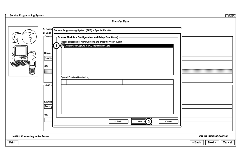
senlice programming system transfer data service programming system (sps) special function control module configuration and setup function(s) please select one or more functions and press the next button wide capture of ecu identication data special function session log m4382: connecting to the sewer... vin: kl1tf4839cb000395
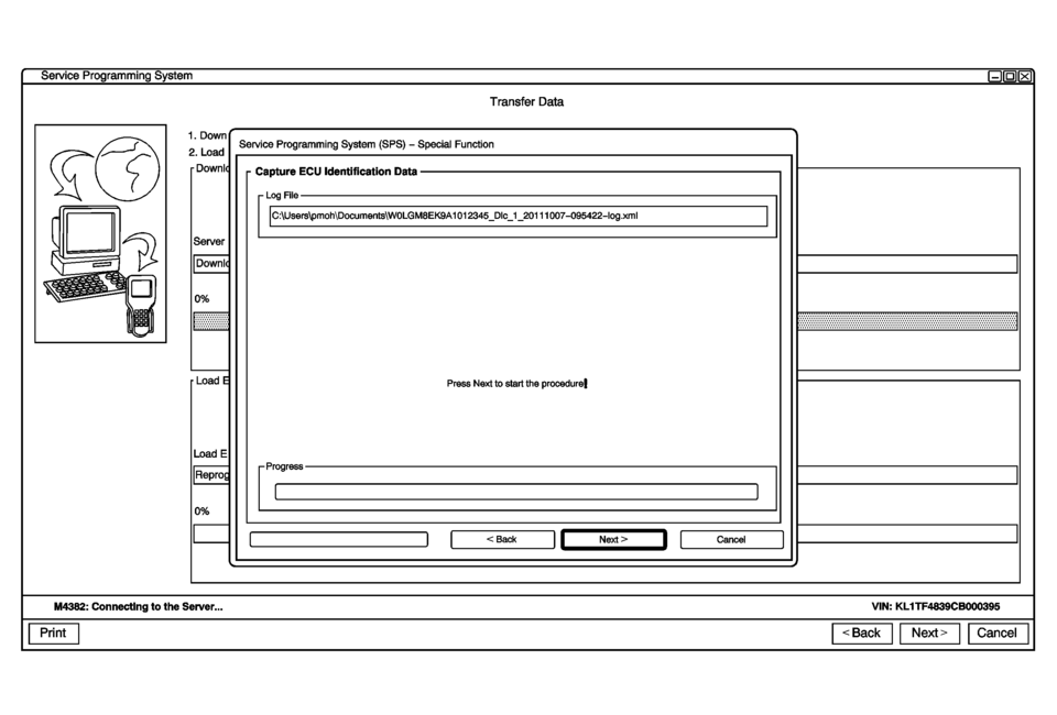
service programming system transfer data service programming system (sps) special function capture ecu identification data log file c:\users\pmoh\documents\wolgm8ek9a1012345_dc_1_201 1007o95422og.xm press next to start the procedural progress m4382: connecting to the sewer... vin: kl1tf4839cb000395
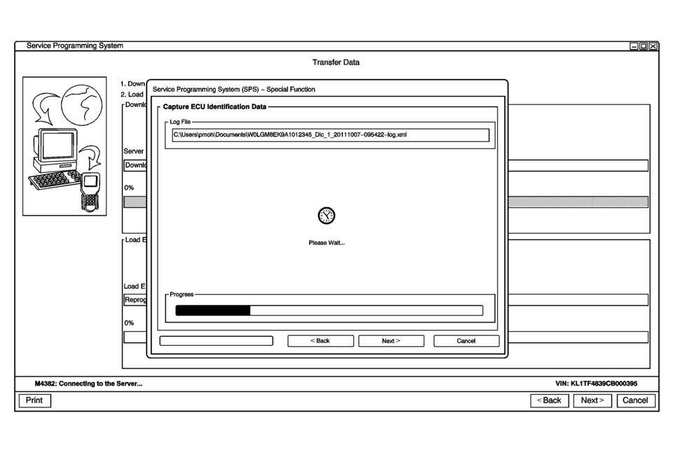
service programming system transfer data service programming system (sps) special function capture ecu identification data log file c:\users\pmoh\documents\wolgm8ek9a1012345_dc_1_201 1007095422log.xm please wait... progress m4382: connecting to the sewer... vin: kl1tf4839cb000395
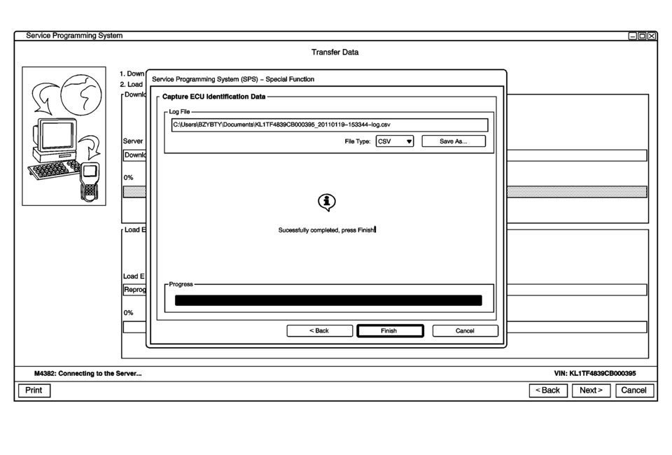
service programming system transfer data service programming system (sps) special function capture ecu ldentlflcatlon data log file c:\users\bzybty\documents\kl1tf4639cb000395_201 101 19153344iog.csv sucessfully completed, press finishl progress m4382: connecting to the sewer... vin: kl1tf4839cb000395
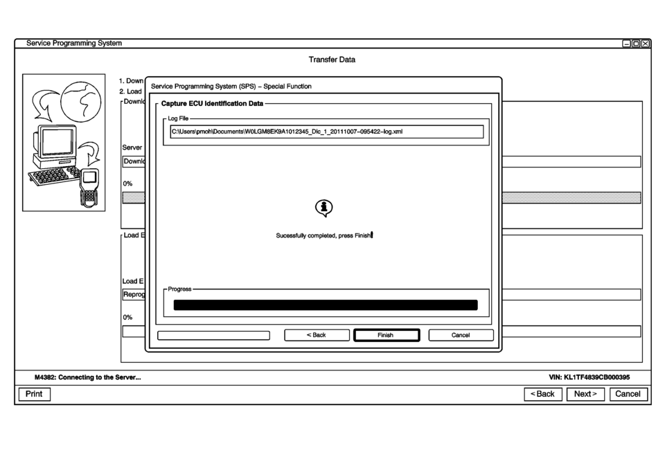
service programming system transfer data service programming system (sps) special function capture ecu ldentlflcatlon data log file c:\users\pmoh\documents\wolgm8ek9a1012345_dc_1_201 10o7095422log.xm sucessfully completed, press m4382: connecting to the sewer... vin: kl1tf4839cb000395
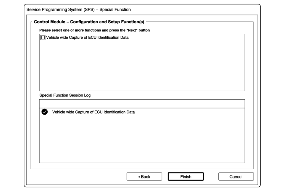
service programming system (sps) special function control module configuration and setup function(s) please select one or more functions and press the next button vehicle wide capture of ecu identification data special function session log vehicle wide capture of ecu identification data
- Select Diagnostic Tool, Programming Process and click “Next”.
- Click “Next”.
- Select Salesmake, Model Year, Vehicle Type, Car Line and click “Next”.
- Verify correct VIN, click “Next”.
- Select BCM in Controller and Programming in Function/Sequence.
- Select Programming Type.
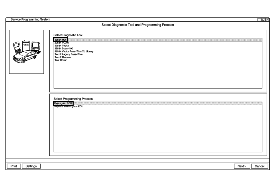
service programming system select diagnostic tool and programming process select diagnostic tool j2534 tech2 j2534 scan100 j2534 vector passthru xl ubrary tech2 legacy pass-thru tech2 remote test driver select programming process
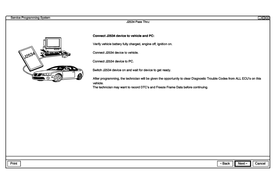
service programming system j2534 pass thru: connect j2534 device to vehicle and pc: verify vehicle battery fully charged, engine off, ignition on. connect j2534 device to vehicle. connect j2534 device to pc. switch j2534 device on and wait for device to get ready. after programming, the technician will be given the opportunity to clear diagnostic trouble codes from all ecus on this vehicle. the technician may want to record dtcs and freeze frame data before continuing.
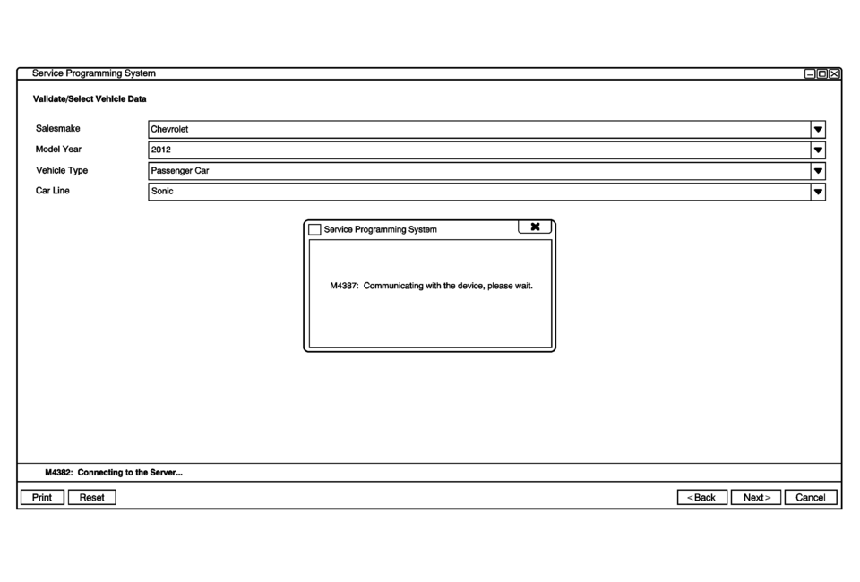
service programming system validate/select vehicle data salesmake chevrolet vehicle type passenger gar service programming system m4387: communicating with the device, please wait.
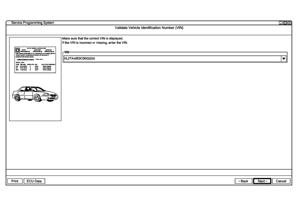
service programming system validate vehicle identification number (vin) make sure that the correct vin is displayed. if the vin is incorrect or missing, enter the vin. eumu-nr kl3ta48e9cboo2255 up comm: arr rnsnums run in sun run
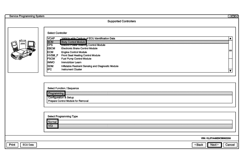
service programming system supported controllers select controller ecu identification data control module electronic brake control module engine control module front seat heating control module fuel pump control module immobilizer learn inatable restraint sensing and diagnostic module instrument cluster select function sequence on rguration setup prepare control module for removal select programming type vin: kl3ta48e9cb002255 data
- “Normal” - (GMNA, South America & Australia)
- “VCI” - (All Regions Except GMNA, South America and Australia)
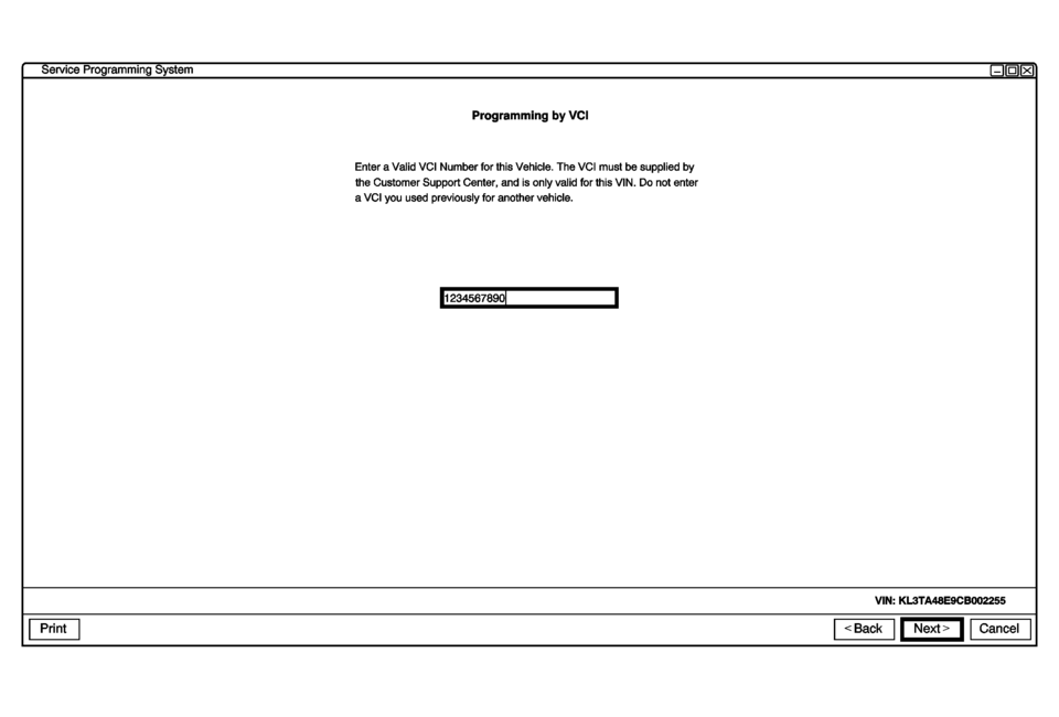
service programming system programming by vci enter valid vci number for this vehicle. the vci must be supplied by the customer support center, and is only valid for this vin. do not enter vci you used previously for another vehicle. 1234567890 vin: kl3ta48e9cboo2255
- Enter the V.C.I which is supplied by the SPS Team. (All regions except GMNA, South America and Australia) click “Next”.
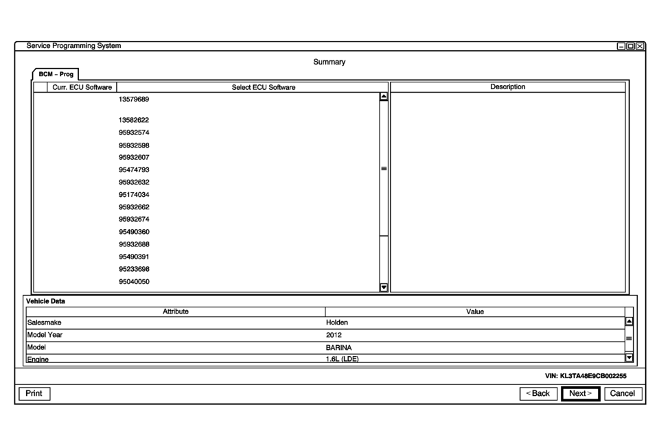
service programming system ecu software seect ecu software 3579689 13582622 95932574 95932598 95932607 95474793 95932632 95174034 95932662 95932674 95490360 95932688 95490391 95233698 95040050 vehicle data salesmake holden model year 2012 model barina enine 1.6l lde
- Confirm the ECU Software in TIS2WEB and Click “Next”.
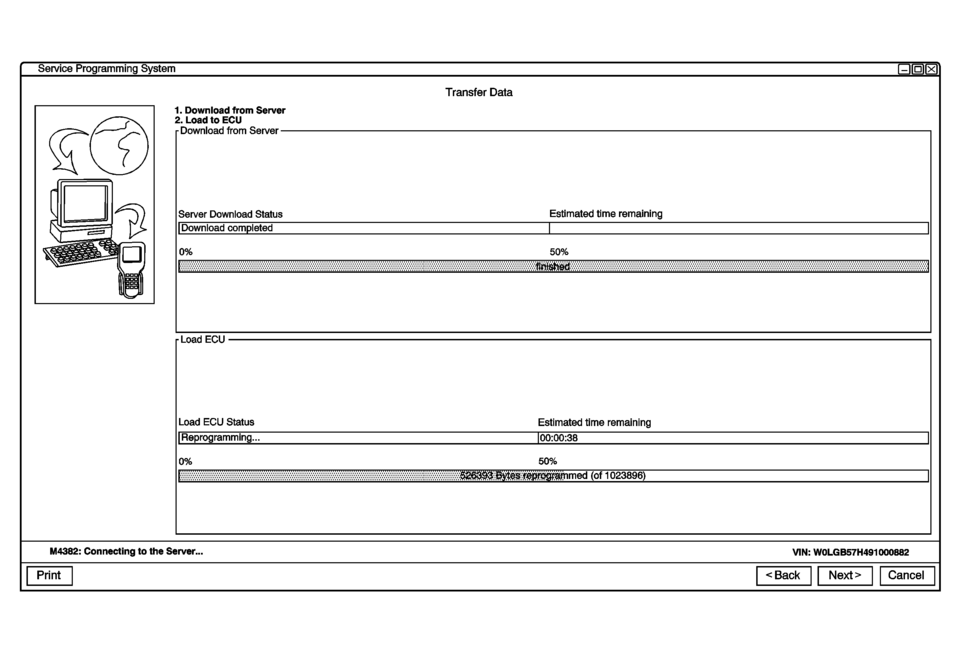
service programming system transfer data 1. download from sewer 2. load to ecu download from server server download status estimated time remaining download 00m eted 0% load ecu status estimated time remaining fteprogramming... 00:00:38 0% m4382: connecting to the sewer... vin: wolgb57h4910oob82
- Programming in progress.
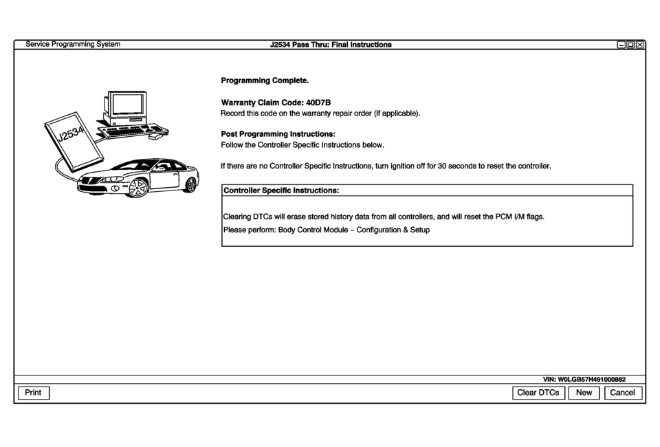
service programming system j2534 pass thru: final instructions programming complete. warranty claim code: 40d7b record this code on the warranty repair order (if applicable). post programming instructions: follow the controller specific instructions below. if there are no controller specific instructions, turn ignition off for 30 seconds to reset the controller. controller specific instructions: clearing dtcs will erase stored history data from all controllers, and will reset the pcm i/m flags. please perform: body control module configuration setup vin: wolgb57h491000882 clear dtcs cancel
- Programming Complete.
Support ProcessNote:
After reprogramming the BCM, it may not recognize the brake pedal application & position. Delete all stored DTC’s after the reprogramming.
Note:
If the BAS Learning is not correctly completed; MDI GDS: Diagnostic>BCM>Reset Functions>”Brake Pedal Position Sensor Learn”.
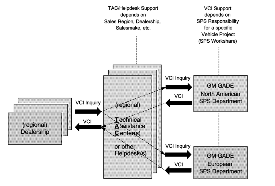
tac/helpdesk support depends on
 Electrical Power Management Description and Operation
Electrical Power Management
The electrical power management is used to monitor and control the charging
system and alert the driver of possible problems within the charging system.
The ...
 Generator Pulley Replacement (LUV)
Generator Pulley Replacement
Callout
Component Name
Preliminary Procedure
Remove the generator. Refer to Generator Replacement. ...
Other materials:
Traction Off Light
This light comes on briefly while starting the engine. If it does not, have the
vehicle serviced by your dealer. If the system is working normally, the indicator
light then turns off.
The traction off light comes on when the Traction Control System (TCS) has been
turned off by pressing and ...
Body Panel Paint Protector Replacement (VGC)
The paint protective film and vehicle surface temperature should be 13?€“32?°C
(55?€“90?°F) for best results.
Automatic car washes should be avoided for at least 24?€‰hours after the
paint protective film application.
Wipe the vehicle surface with isopropyl alcohol or fl ...
Front Side Door Window Weatherstrip Replacement
Front Side Door Window Weatherstrip Replacement
Callout
Component Name
Preliminary Procedures
Remove front side door trim panel. Refer to Front Side Door Trim
Replacement.
Remove the outside rearview mirror. Refer to Outs ...

0.0071