Chevrolet Sonic Repair Manual: Instrument Panel Airbag Arming Status Display Replacement
|
Callout |
Component Name |
|---|---|
|
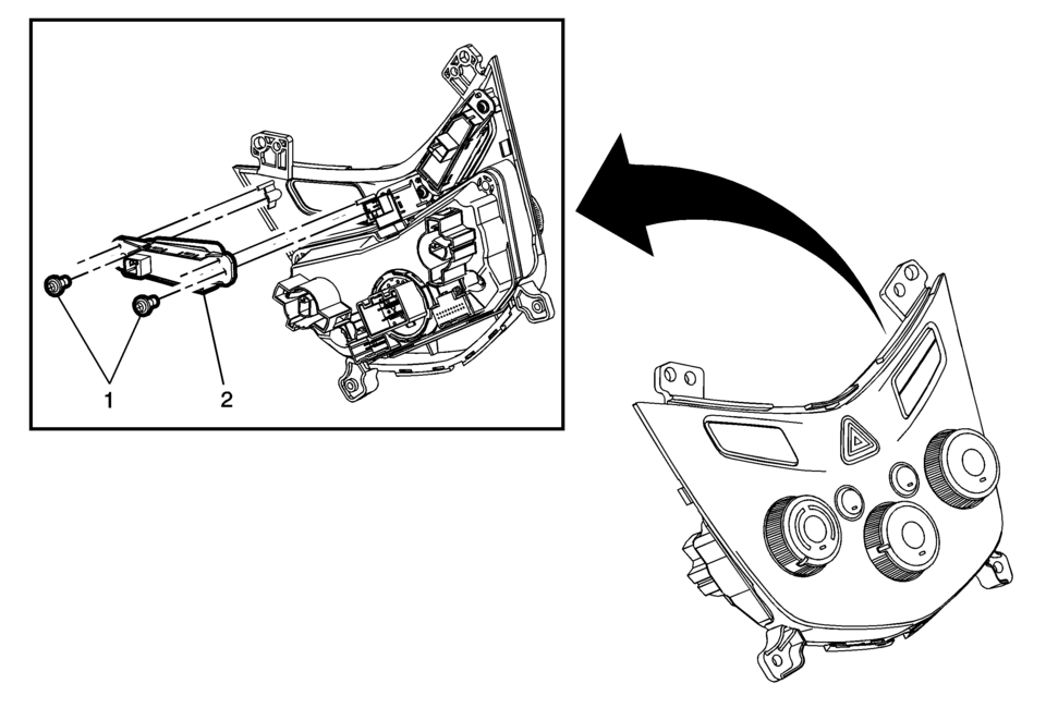
Preliminary Procedure
Remove the heater and air conditioning control. Refer to Heater and Air Conditioning Control Replacement. |
|
|
1 |
Instrument Cluster Display Switch Fastener (Qty:?€‰2) Caution: Refer to Fastener Caution. |
|
2 |
Inflatable Restraint Instrument Panel Module Indicator Procedure
Disconnect the electrical connector. |
 Front Seat Outboard Seat Back Airbag Replacement
Front Seat Outboard Seat Back Airbag Replacement
Callout
Component Name
Warning: Following the deployment of a side impact air ...
 Instrument Panel Lower Airbag Replacement - Driver Side
Instrument Panel Lower Airbag Replacement - Driver Side
Callout
Component Name
Warning: Refer to SIR Inflator Module Handling ...
Other materials:
Protecting Exterior Bright Metal Moldings
Caution
Failure to clean and protect the bright metal moldings can result in a hazy
white finish or pitting. This damage would not be covered by the vehicle warranty.
The bright metal moldings on the vehicle are aluminum. To prevent damage always
follow these cleaning instructions:
Be sure ...
Front Wheel Drive Shaft Seal Replacement - Torque Converter Housing Side
Front Wheel Drive Shaft Seal Replacement - Torque Converter Housing
Side
Callout
Component Name
1
Front Wheel Drive Shaft Oil Seal Assembly
Special Tools
DT-23129 Universal Seal Remover
DT-47790 Seal Insta ...
4WD shift switch
Example
Select the appropriate 4WD mode in the Nissan Armada by shifting the 4WD
switch to AUTO, 4H, or 4L (if equipped), depending on current road and driving
conditions. This flexibility allows the Nissan Armada to adapt to both on-road
and off-road environments.
When AUTO mode ...

0.0065