Chevrolet Sonic Repair Manual: Parking Brake Lever Replacement
- Removal Procedure
-
- Remove the front floor console. Refer to Front Floor Console Replacement.
- Ensure that the park brake lever is in the fully released position.
- Disconnect the electrical connector from the park brake warning lamp switch.
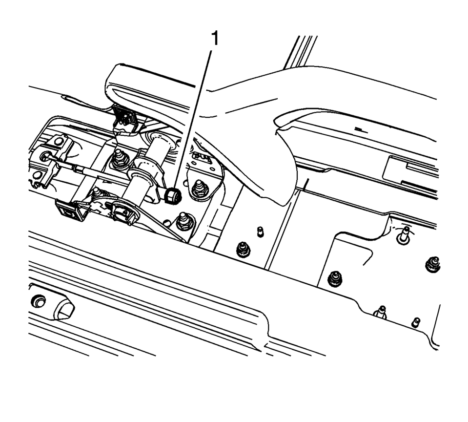
- Using ONLY HAND TOOLS, loosen the adjusting nut (1) completely to the end of the front cable threaded rod.
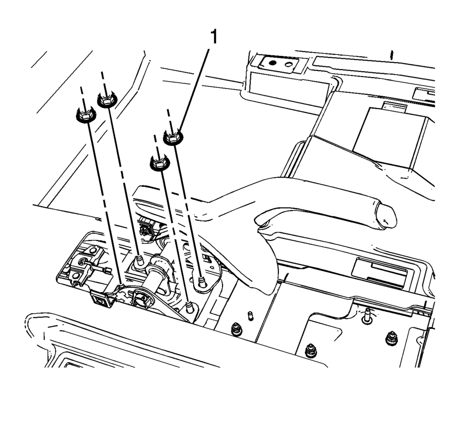
- Remove the park brake lever mounting nuts (1).
- While removing the front cable threaded rod from the park brake lever assembly, remove the park brake lever assembly from the vehicle.
- Installation Procedure
-
- While intstalling the front cable threaded rod to the park brake lever assembly, install the park brake lever assembly to the vehicle.
- Install the park brake lever mounting nuts (1) and tighten to 22 Y
(16 lb ft)
.
- Connect the electrical connector to the park brake warning lamp switch.
- Loosely install the adjusting nut (1) to front cable threaded rod.
- Adjust the park brake cable tension. Refer to Parking Brake Adjustment.
- Install the front floor console. Refer to Front Floor Console Replacement.
Caution:
Refer to Fastener Caution.
 Parking Brake Indicator Switch Replacement
Removal Procedure
Remove the front floor console. Refer to Front Floor Console Replacement.
Ensure that the park brake lever is in the fully released position.
Disconnect th ...
 Parking Brake Cable Replacement (Disc Brake)
Removal Procedure
Remove the front floor console. Refer to Front Floor Console Replacement.
Ensure that the parking brake lever is in the fully released position.
Using ...
Other materials:
Rear Bumper Fascia Outer Guide Replacement (Sedan)
Rear Bumper Fascia Outer Guide Replacement
Callout
Component Name
Warning: Refer to Eye Protection Warning.
Preliminary Procedure
Remove the rear bumper fascia. Refer to Rear Bumper Fascia Replacement.
...
Brake Pressure Modulator Valve Replacement
Removal Procedure
Warning: Refer to Brake Fluid Irritant Warning.
Caution: Refer to Brake Fluid Effects on Paint and Electrical
Components Caution.
Caution: Always connect or disconnect the wiring harness connector
from the EBCM/EBTCM with the ignition switch ...
Assist grips
The Nissan Armada assist grips are strategically positioned above the front passenger
door and rear side doors to provide additional support for passengers during travel.
CAUTION
Do not use the Nissan Armada assist grips as a support when entering or exiting
the vehicle. Improper use may d ...

0.0055