Chevrolet Sonic Repair Manual: Rear Wheel Speed Sensor Replacement
- Removal Procedure
-
Warning:
Refer to Brake Dust Warning.
- Raise and support the vehicle. Refer to Lifting and Jacking the Vehicle.
- Remove the tire and wheel assembly. Refer to Tire and Wheel Removal and Installation.
- Remove the rear wheel speed sensor harness connector cover nuts (1).
- Remove the rear wheel speed sensor harness connector cover (1).
- Clean the rear drum brake area around the wheel speed sensor of any accumulated dirt and debris.
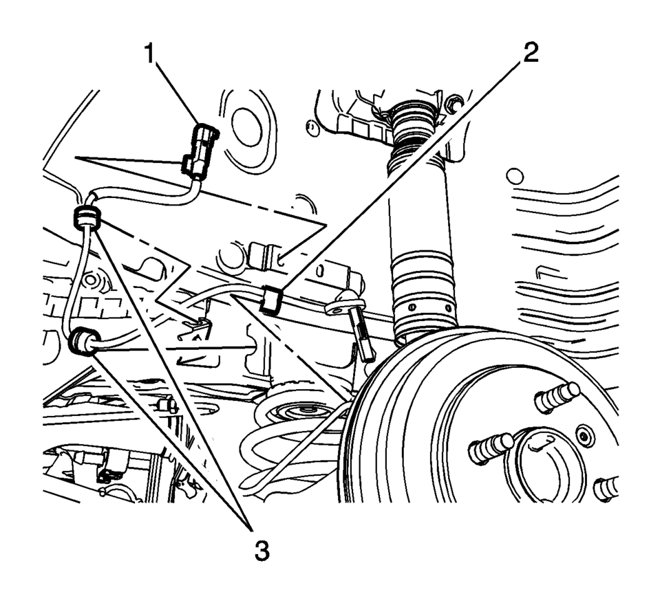
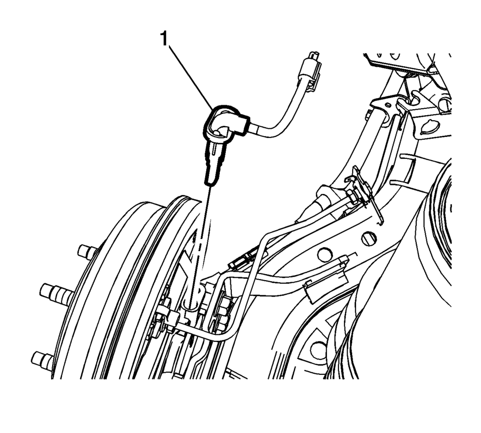
- Disconnect the wheel speed sensor electrical connector (1) and release the connector from the wheelhouse bracket.
- Release the wheel speed sensor harness retainer (2) from the wheel cylinder brake pipe.
- Release the wheel speed sensor harness grommets (3) from the bracket.
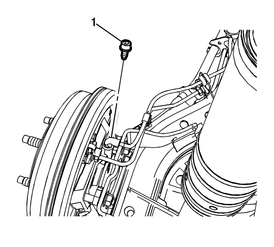
- Remove the wheel speed sensor bolt (1).
- Remove the wheel speed sensor (1) from the rear drum brake spacer by pulling the sensor straight upward using a slight twisting motion.


- Installation Procedure
-
- Install the wheel speed sensor (1) to the rear drum brake spacer.
- Install the wheel speed sensor bolt (1) and tighten to 8 Y (71 lb in)
.
- Connect the wheel speed sensor electrical connector (1) and install the connector to the wheelhouse bracket.
- Install the wheel speed sensor harness retainer (2) to the wheel cylinder brake pipe.
- Install the wheel speed sensor harness grommets (3) to the bracket.
- Install the rear wheel speed sensor harness connector cover (1).
- Install the rear wheel speed sensor harness connector cover nuts (1)
and tighten to 2 Y (18 lb in)
.
- Install the tire and wheel assembly. Refer to Tire and Wheel Removal and Installation.
- Perform the Diagnostic System Check - Vehicle.
Caution:
Refer to Fastener Caution.
Note:
If the wheel speed sensor grommets are equipped with a molded rib, position the grommets with the rib at the open end of the wheel speed sensor harness brackets. Do not twist the wheel speed sensor harness.
 Output Speed Sensor Replacement
Output Speed Sensor Replacement
Callout
Component Name
Preliminary Procedure
Remove the control valve body. Refer to Control Va ...
 Vehicle Speed Sensor Replacement
Vehicle Speed Sensor Replacement
Callout
Component Name
1
Engine Wiring Harness Bracket Nut
Caution: Refer to Fa ...
Other materials:
Rear Compartment Lid Nameplate Replacement (Sedan)
Rear Compartment Lid Nameplate Replacement
Callout
Component Name
1
Rear Compartment Lid Nameplate
Caution: Refer to Exterior Trim Emblem Removal Caution.
Procedure
The part and surface should be ...
Liftgate Hinge Replacement
Liftgate Hinge Replacement
Callout
Component Name
Preliminary Procedures
Remove the liftgate. Refer to Liftgate Replacement.
Lower the rear of the headliner to access the inner bolts. Refer
to Headlining Trim Panel Replac ...
Generator Replacement (LUW)
Removal Procedure
Disconnect the negative battery cable. Refer to Battery Negative Cable
Disconnection and Connection.
Raise and support the vehicle. Refer to Lifting and Jacking the Vehicle.
Remove the drive belt. Refer to Drive Belt Replacement.
Remove t ...

0.006