Chevrolet Sonic Repair Manual: Shift Control Housing Replacement
- Removal Procedure
-
- Set the parking brake.
- Shift the transmission to the Neutral position.
- Remove the battery tray. Refer to Battery Tray Replacement.
- Remove the brake master cylinder assembly from the power brake booster. Refer to Master Cylinder Replacement.
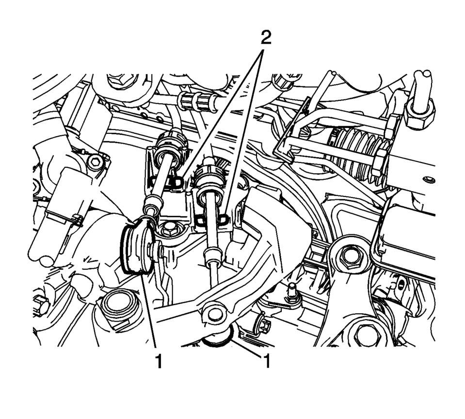
- Disconnect the shift lever and selector lever cable end (1) from the transmission shift lever and selector lever.
- Pull the cable retainers (2) to release the shift lever and selector lever cable from the shift lever and selector lever cable bracket.
- Disconnect the shift lever and selector lever cable from the shift lever and selector lever cable bracket.
- Disconnect the electrical connector from the shift control housing assembly.
- Remove the backup lamp switch. Refer to Backup Lamp Switch Replacement.
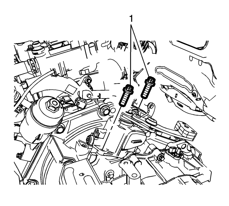
- Remove the two shift control housing assembly fasteners (1).
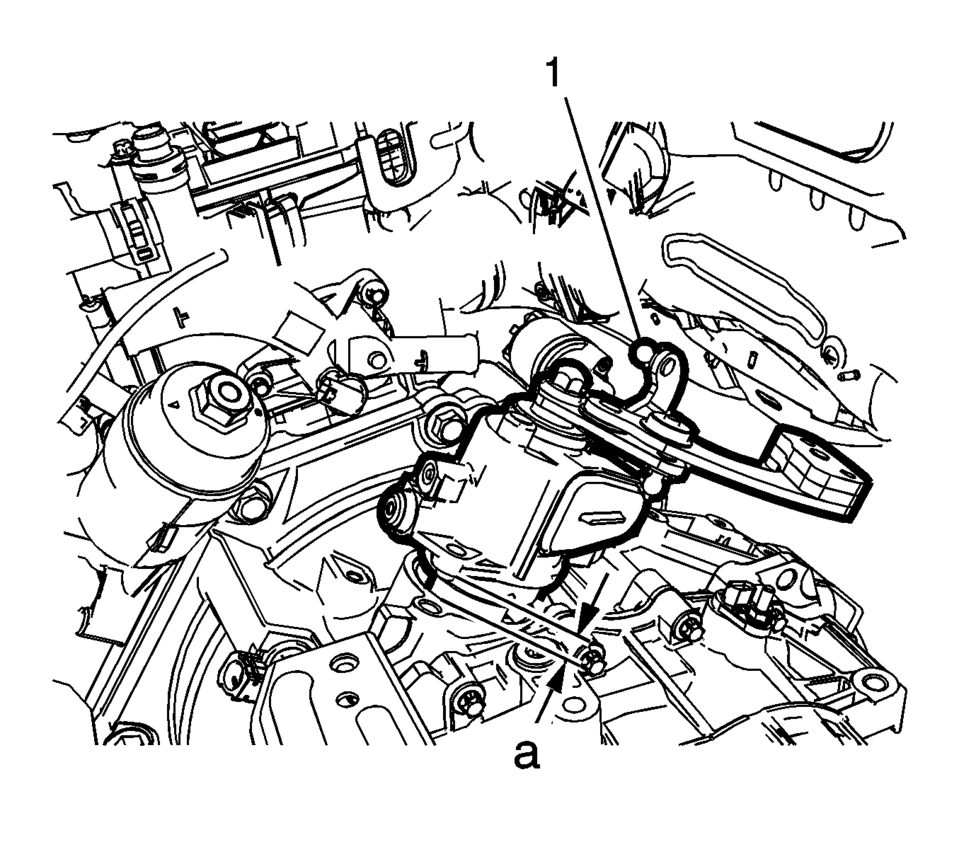
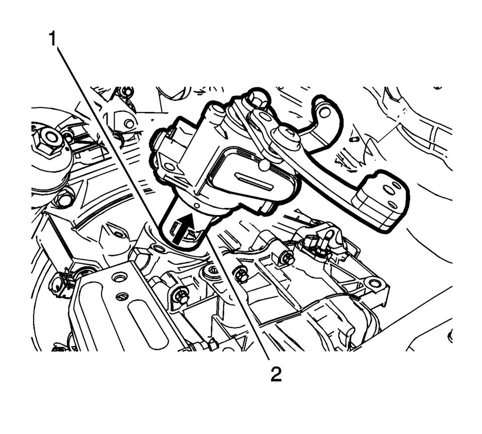
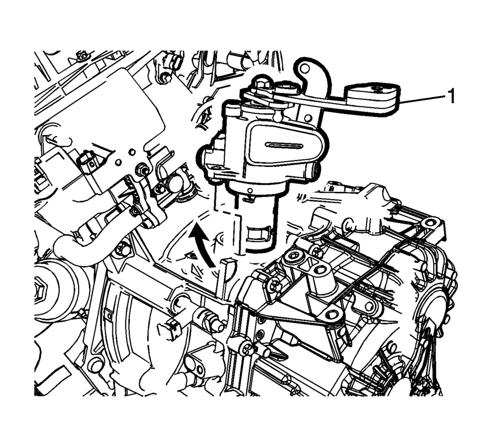
- Slowly and Carefully lift the shift control housing assembly (1) no farther than 3 cm (1 inch) shown by dimension (A).
- Holding the shift control housing assembly (1) at the specified height, rotate the assembly clockwise approximately 30?5 degrees.
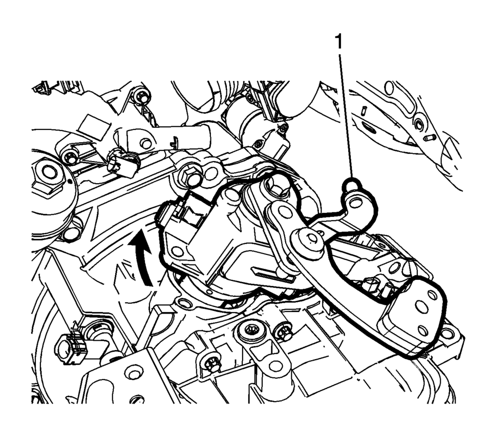
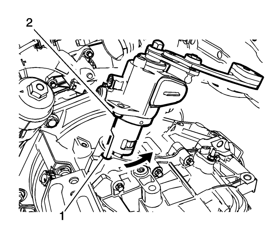
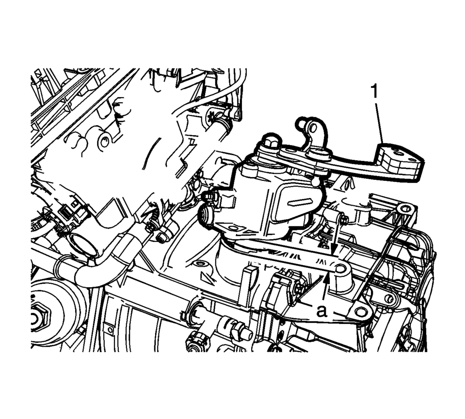
- Slowly and Carefully lift the shift control housing assembly (2) until the lower edge of the upper shift finger (1) is even with the transmission case.
- Turn the shift control housing assembly counterclockwise approximately 30?5 degrees until the guide peg (2) is in line with the threaded hole (1).
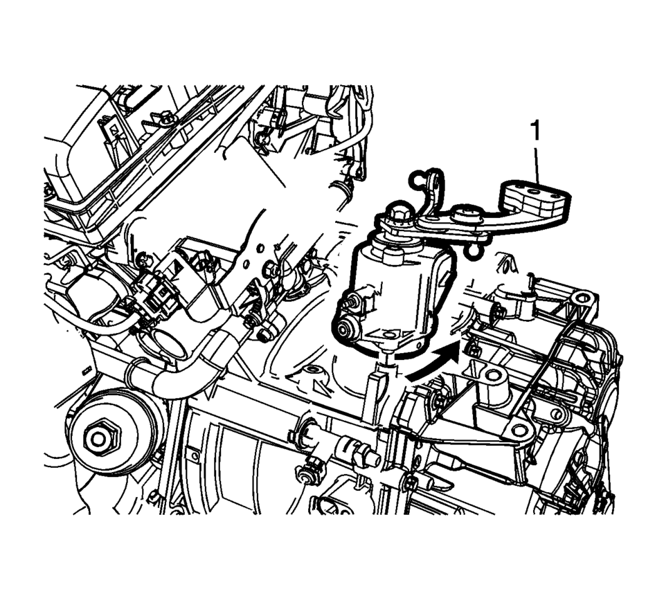
- Slowly and Carefully remove the shift control housing assembly from the transmission.
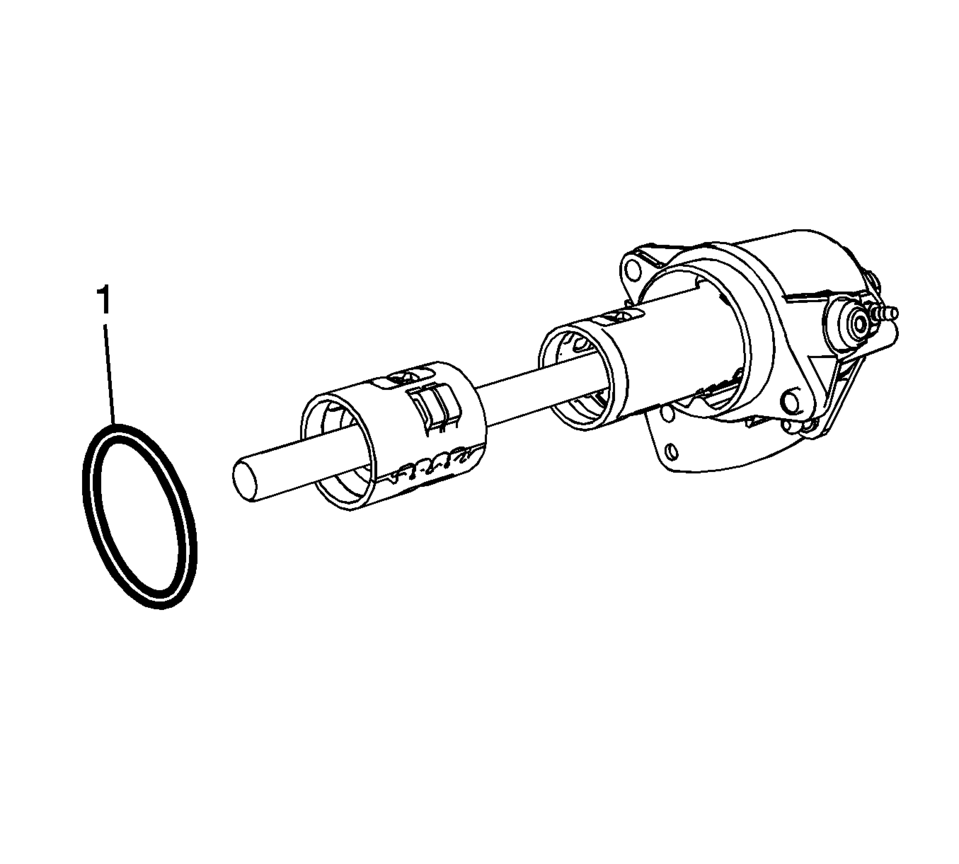
- If reinstalling the shift control housing assembly, remove and discard the O-ring (1).
- Installation Procedure
-
- If reinstalling the shift control housing assembly, install a New O-ring (1).
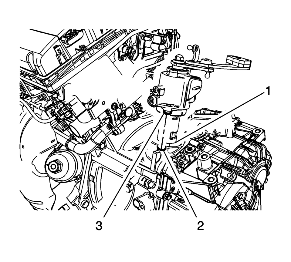
- Align the guide peg (3) in line with the threaded hole (2), then Slowly and Carefully insert the shift control housing assembly in the transmission case, STOP when the lower edge of the upper shift finger (1) is even with the transmission case.
- Turn the shift control housing assembly clockwise approximately 30?5 degrees.
- Lower the shift control housing assembly (1) no farther than 3 cm (1 inch) from the transmission case shown by dimension (A).
- Holding the shift control housing assembly (1) at the specified height, rotate the assembly counterclockwise approximately 30?5 degrees to align the guide peg with the threaded hole.
- Slowly and Carefully lower the shift control housing until seated in the transmission case.
- Install the two shift control housing assembly fasteners (1)
and tighten to 20 Y (16 lb ft)
.
- Connect the shift lever and the selector lever cable ends (1) to the transmission shift lever and the selector lever.
- Install the brake master cylinder assembly to the power brake booster. Refer to Master Cylinder Replacement.
- Install the backup lamp switch. Refer to Backup Lamp Switch Replacement.
- Connect the electrical connector to the shift control housing assembly.
- Install the battery tray. Refer to Battery Tray Replacement.
- Verify correct operation of the transmission control assembly.
Note:
Only insert the shift control housing assembly until the lower edge of the upper shift finger (1) is even with the transmission case.
Caution:
Refer to Fastener Caution.
 Selector and Shift Lever Cable Bracket Replacement
Removal Procedure
Remove the battery tray. Refer to
Battery Tray Replacement.
Disconnect the shift lever and selector lever cable
end (1) from the transmissio ...
 Special Tools
Illustration
Tool Number/Description
3-0207944
Main Shaft Tapered Bearing Insert Tool
3950628 ...
Other materials:
Body Lock Pillar Upper Trim Panel Replacement (Hatchback)
Body Lock Pillar Upper Trim Panel Replacement
Callout
Component Name
Preliminary Procedure
Disable the SIR system. Refer to SIR Disabling and Enabling.
1
Inflatable Restraint Airbag Cover
...
Rear Seat Head Restraint Guide Replacement
Rear Seat Head Restraint Guide Replacement
Callout
Component Name
Preliminary Procedure
Remove the rear seat head restraint. Refer to Rear Seat Head Restraint
Replacement
1
Rear Seat Head Restra ...
Valve Guide Reaming, and Valve and Seat Grinding
Valve Cleaning Procedure
Use soft bristle wire brush to clean any carbon build-up from the valve
head. DO NOT use a wire brush on any part of the valve stem. The valve stem
is chrome plated to provide enhanced wear characteristics. Wire brushing
the stem could remove the chr ...

0.006