Chevrolet Sonic Repair Manual: Steering Linkage Inner Tie Rod Replacement
|
Callout |
Component Name |
|---|---|
Preliminary Procedures
|
|
|
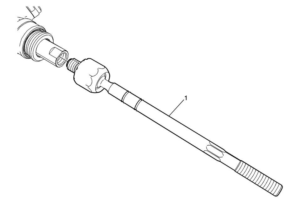
1 |
Steering Linkage Inner Tie Rod Caution: Do not change the steering gear preload adjustment before moving the inner tie rod from the steering gear. Changing the steering gear preload adjustment before moving the inner tie rod could result in damage to the pinion and the steering gear. Caution: Refer to Fastener Caution.
100 Y (74 lb ft) |
 Steering Linkage Inner Tie Rod Inspection
Special Tools
GE-8001 Dial Indicator Set
For equivalent regional tools, refer to Special Tools.
Note: This inspection procedure does not supersede local government
required inspection ...
 Steering Linkage Outer Tie Rod Inspection
Special Tools
GE-8001 Dial Indicator Set
For equivalent regional tools, refer to Special Tools.
Note: This inspection procedure does not supersede local government
required inspection ...
Other materials:
Front Seat Cushion Inner Trim Panel Replacement
Front Seat Cushion Inner Trim Panel Replacement
Callout
Component Name
1
Driver or Passenger Seat Inner Recliner Finish Cover Cap
Procedure
Use a flat-bladed tool to release the cap from the recliner cover.
...
Heater Outlet Hose Replacement (LUV)
Heater Outlet Hose Replacement
Callout
Component Name
Preliminary Procedures
Drain the engine coolant. Refer to Cooling System Draining and Filling.
Remove the air cleaner assembly. Refer to Air Cleaner Assembly Replacemen ...
Engine Flywheel Replacement
Engine Flywheel Replacement
Callout
Component Name
Preliminary Procedure
Remove the clutch pressure and driven Plate . Refer to Clutch Pressure
and Driven Plate Replacement.
Special Tools
EN-652 Flywheel Holder
...

0.0052